


Druckmessgerät PG-35H

- ●Um einen Kauf zu tätigen, wenden Sie sich an die Verteiler
oder nutzen Sie den stehenden Online-Shops unten.
Verkaufskanal Überprüfen Sie die Verteiler.- VERKAUFSKANALKlicken Sie hier, um den Verteiler zu überprüfen.


Pressure gauge PG-35H
- For high pressure
- For corrosive gases and liquids compatible with SUS316L stainless steel diaphragm
- Compact
- Light weight
- Drip-proof structure (30 mm sq • 200 g • IP65)
- Low consumption by nondisplay mode
- Set data protection by panel lock function
|
|
General specifications
- Unless otherwise specified, the specs are defined at an ambient temperature of 25 ± 5 °C and excitation voltage of 12 VDC.
| Model number | 104R | 354R |
|---|---|---|
| Pressure reference | Gauge | |
| Pressure medium | Pressure Port R2: Corrosive hydraulic oil compatible with Iron or Nickel Pressure Port G3: Corrosive gases/liquids compatible with Iron and Nickel |
|
| Rated pressure range | - 0.1 ~ 10 MPa | - 0.1 ~ 35 MPa |
| Maximum pressure | 20 MPa | 50 MPa |
| Break-down pressure | 40 MPa | 50 MPa |
| Operating temp. range | - 10 ~ 50 °C | |
| Compensated temp. range | 0 ~ 50 °C | |
| Operating humidity | 35 ~ 85 %RH(No condensation) | |
| Protection grade | IP65 | |
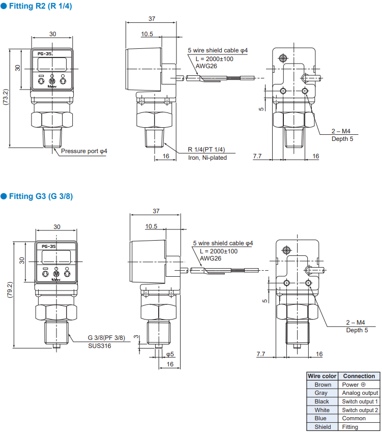
| Type of mounting | R 1/4, G 3/8 | |
| Pressure port | Stem mount, Back mount | |
| Material of pressure port attachment | SUS316L | |
| Net weight | Approx. 200 g(Including 2 m cable) | |
| Thermal error | ± 3 %F.S. (0 ~ 50 °C) | |
| Insulation resistance | 100 MΩ minimum | |
| Dielectric strength | 500 VAC 1 minute | |
| Input voltage | 10.8 ~ 30 VDC(Including ripple percentage) | |
| Consumption current | 50 mA maximum | |
Display
- Unless otherwise specified, the specs are defined at an ambient temperature of 25±5 °C and excitation voltage of 12 VDC.
| Model number | 104R | 354R |
|---|---|---|
| Display element | Full 3-digit LED | |
| Rated display range | - 0.10 ~ 9.99 MPa | - 00.1 ~ 35.0 MPa |
| Multiplier settings | Max. 11 settings | |
| Display cycle | Approx. 4 times/s | |
| Negative pressure display | “–” LED is ON | |
| Display accuracy | ± 2 % | |
Switch output
- Unless otherwise specified, the specs are defined at an ambient temperature of 25±5 °C and excitation voltage of 12 VDC.
| Output status | NPN / PNP 2-point output (Transistor, Open collector output) |
|---|---|
| Output mode | Separate mode / window comparator mode |
| Switching capacity | 30 VDC 100 mA |
| Residual voltage | 1.2 V maximum (NPN), 2.2 V maximum (PNP) |
| State indication | Output 1 (Green LED), Output 2 (Red LED) Lighted when output is ON. |
| Switch hysteresis | 0 ~ 300 counts(Adjustable) |
| Repeatability | ± 0.2 %F.S. ± 1 count |
| Response | Approx. 5, 25, 250, 2500 ms Adjustable |
Analog output
- Unless otherwise specified, the specs are defined at an ambient temperature of 25±5 °C and excitation voltage of 12 VDC.
| Output mode | 3 modes |
|---|---|
| Output voltage V zero : Pin=0, V span : Pin=0 〜Pin (H) |
1 ~ 5 V (R mode 104R-ZERO:1.04 ± 0.2 V, SPAN: 3.96 ± 0.2 V, 354R-ZERO:1.01 ± 0.2V, SPAN: 3.99 ± 0.2 V ; G mode ZERO: 1 ± 0.2 V, SPAN : 4 ± 0.2 V) ※ The accuracy at V mode is not guaranteed. |
| Impedance | 10 kΩ |
| Resolution | 1/204(Approx. 20 mV/ Approx. 0.5 % F.S.) |
ENVIRONMENTAL CHARACTERISTICS
| Test item | Test conditions | Permissible change |
|---|---|---|
| Vibration | 10 ~ 500 Hz, 98.1 m/s2 or 1.5 mm P-P, 3 directions for 2 hours each |
Pressure indication,switch operating points and analog output variation : ± 2 %F.S. maximum each after test |
| Shock | 490 m/s2 , 3 directions for 3 times each | |
| Moisture resistance | 40 °C, 90 ~ 95 %RH, 240 hrs | |
| Pressure cycling | 0 ~ Rated pressure, 106 cycles |
MODEL NUMBER DESIGNATION
| PG - 35H- | 104 | R- | N | R2 | B |
|---|---|---|---|---|---|
|
Series name |
Pressure range 104: - 0.1 ~ 10 MPa 354: - 0.1 ~ 35 MPa |
Pressure reference R: Compound pressure (Negative pressure ~ Positive pressure) |
Switch output interface N: NPN open collector P: PNP open collector |
Fitting R2: R 1/4 G3: G 3/8 |
Port Blank: Stem mount B: Back mount |
LIST OF MODEL NUMBERS
| Part No. | Rated pressure range | Pressure reference | Fitting | Fitting direction | SW output interface | CAD |
|---|---|---|---|---|---|---|
| PG-35H-104R-NR2 | -0.1 ~ 35 MPa | Gauge (Compound) | R2 (R 1/4) | Stem mount | NPN | |
| PG-35H-104R-PR2※ | -0.1 ~ 35 MPa | Gauge (Compound) | R2 (R 1/4) | Stem mount | PNP | |
| PG-35H-104R-NG3 | -0.1 ~ 35 MPa | Gauge (Compound) | R2 (R 1/4) | Stem mount | NPN | |
| PG-35H-104R-PG3※ | -0.1 ~ 35 MPa | Gauge (Compound) | R2 (R 1/4) | Stem mount | PNP | |
| PG-35H-354R-NR2 | -0.1 ~ 35 MPa | Gauge (Compound) | G3 (G 3/8) | Stem mount | NPN | |
| PG-35H-354R-PR2※ | -0.1 ~ 35 MPa | Gauge (Compound) | G3 (G 3/8) | Stem mount | PNP | |
| PG-35H-354R-NG3 | -0.1 ~ 35 MPa | Gauge (Compound) | G3 (G 3/8) | Stem mount | NPN | |
| PG-35H-354R-PG3※ | -0.1 ~ 35 MPa | Gauge (Compound) | G3 (G 3/8) | Stem mount | PNP | |
| PG-35H-104R-NR2B※ | -0.1 ~ 35 MPa | Gauge (Compound) | R2 (R 1/4) | Back mount | NPN |
|
| PG-35H-104R-PR2B※ | -0.1 ~ 35 MPa | Gauge (Compound) | R2 (R 1/4) | Back mount | PNP |
|
| PG-35H-104R-NG3B※ | -0.1 ~ 35 MPa | Gauge | R2 (R 1/4) | Back mount | NPN |
|
| PG-35H-104R-PG3B※ | -0.1 ~ 35 MPa | Gauge | R2 (R 1/4) | Back mount | PNP |
|
| PG-35H-354R-NR2B※ | -0.1 ~ 35 MPa | Gauge | G3 (G 3/8) | Back mount | NPN |
|
| PG-35H-354R-PR2B※ | -0.1 ~ 35 MPa | Gauge | G3 (G 3/8) | Back mount | PNP |
|
| PG-35H-354R-NG3B※ | -0.1 ~ 35 MPa | Gauge | G3 (G 3/8) | Back mount | NPN |
|
| PG-35H-354R-PG3B※ | -0.1 ~ 35 MPa | Gauge | G3 (G 3/8) | Back mount | PNP |
|
Marked "※" is manufactured upon receipt of order basis.
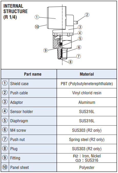
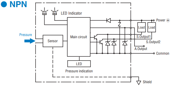
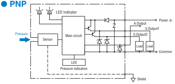
INTERNAL ELECTRICAL SCHEMATICS
|
|
|
|
SELECTION OF DISPLAY MULTIPLIER
- The last digit/letter represents the selection code : Blinking red LED indicates negative pressure.
|
|
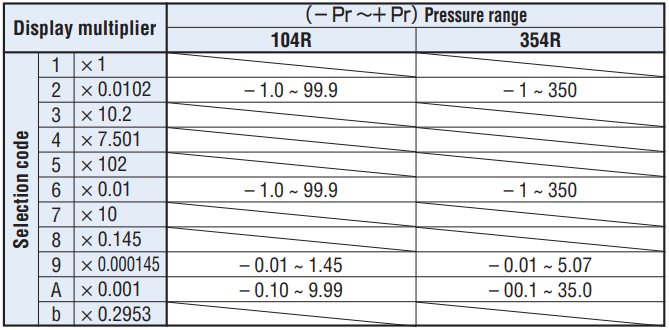
- Diagonal column: Display multiplier cannot be selected due to resolution and number of digits.
- (Selection code is not indicated either.) Selection code is set at “A” prior to shipment.
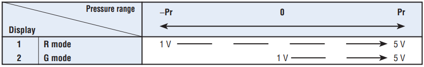
ANALOG OUTPUT MODE
Selection code is set at “G” prior to shipment.
|
|
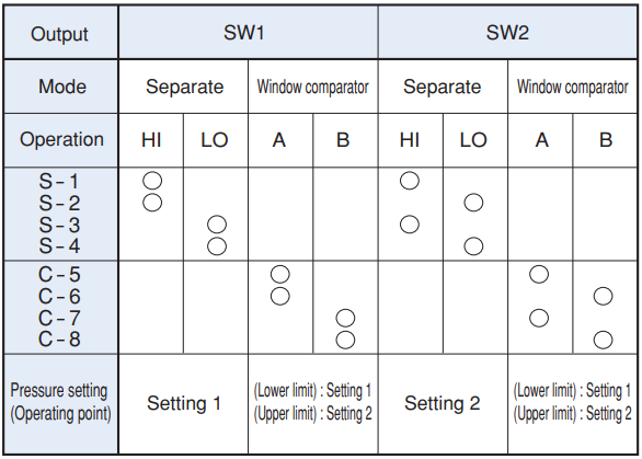
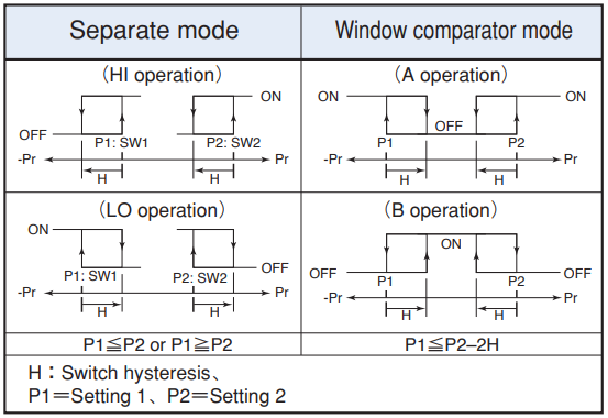
SWITCH OUTPUT MODE
|
|
|
|
- Note 1. In the Separate Mode, setting 1 corresponds to SW1, and Setting 2 corresponds to SW2.
- Note 2. In the Window Comparator Mode, the minimum value for SW1 and SW2 corresponds to Setting 1 and the maximum value corresponds to Setting 2.
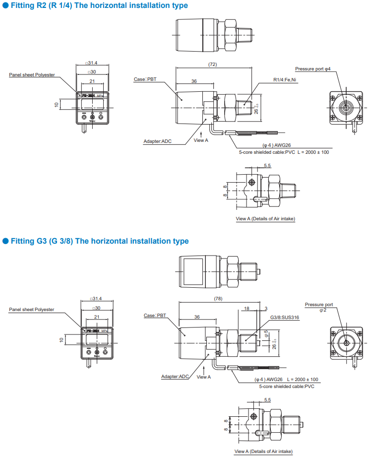
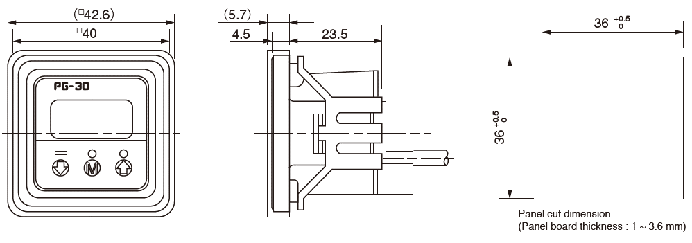
OUTLINE DIMENSIONS
ACCESSORIES (Sold separately)
| Name | Series name | Contents | Applicable model |
|---|---|---|---|
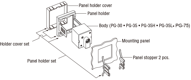
| Panel holder set | ACPG-003 | Panel holder cover Panel holder Panel stopper (2 pcs.) |
PG-30 · PG-35 · PG-75 · PG-35H · PG-35L |
| Holder cover set (For protecting gauge operating panel) |
ACPG-004 | Panel holder cover Panel holder |
PG-30 · PG-35 · PG-75 · PG-35H · PG-35L |
| Holder stopper set | ACPG-007 | Panel holder Panel stopper (2 pcs.) |
PG-30 · PG-35 · PG-75 · PG-35H · PG-35L |
HOW TO MOUNT OPTIONAL ACCESSORIES (Sold separately)
◆PG-30 • PG-35 • PG-35H • PG-35L • PG-75 Panel cut holder set & holder cover set
◆Panel holder cover set
Piping
- Use a wrench on the aluminum die-casting. Do not hold the plastic case when tightening.
- Apply sealing tape at the male screw area (R2 type) to protect against air leaks.
Unterlagen
- ●Die oben genannten Inhalte können ohne vorherige Ankündigung geändert werden.
Produkte
