


Rocker switch SLE10

- ●Um einen Kauf zu tätigen, wenden Sie sich an die Verteiler unten.
Verkaufskanal Überprüfen Sie die Verteiler.- VERKAUFSKANALKlicken Sie hier, um den Verteiler zu überprüfen.
Rocker switch with current capacity of 10 A
-
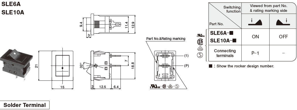
C-US UL , CSA , VDE and SEMKO approved products
UL File No.E43275
CSA File No.LR38341
VDE License No.120752
SEMKO File No.SE-S-2101218R2 -
Snap-in panel mounting
-
Compact size is suited for space-saving design.
-
Best suited for power supply of equipment.
-
Dust-proof type
-
Breaking distance is 3 mm or over.
Specifications
| Rating | Max.: 125 VAC 10A / 250 VAC 5 A (Resistive load) Min.: 5 VAC/DC 10 mA (Resistive load) |
|---|---|
| Initial contact resistance | 20 mΩ max. (1 A 2 ~ 4 VDC) |
| Dielectric strength | 1,500 VAC 1 minute (Between terminals) |
| Insulation resistance | 100 MΩ min. (Between terminals) (500 VDC) |
| Electrical life | 10,000 cycles |
| Operating force | 2.45 ~ 12.7 N |
| Operating temperature range | - 25 ~ + 85 ℃ |
| Storage temperature range | - 40 ~ + 85 ℃ |
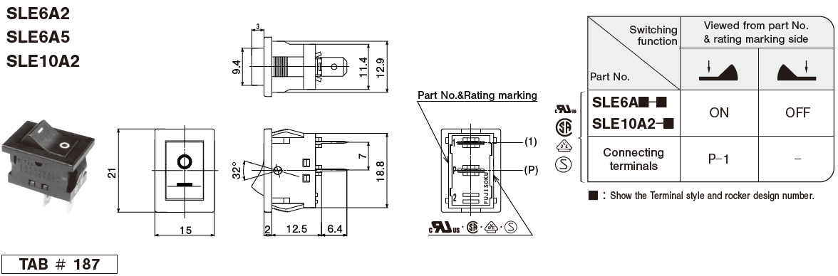
Part Number Designation
| SLE | 10 | A | 2 | - 5 |
|---|---|---|---|---|
|
Series |
Current 10: 10 A |
Switching function A: ON - OFF |
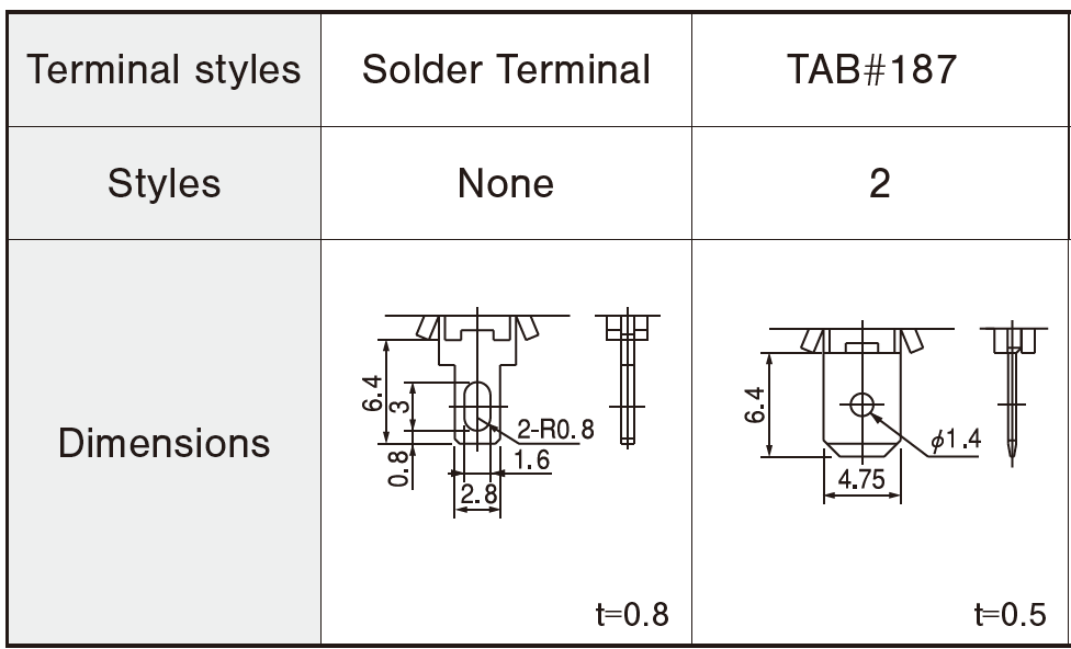
Terminal style Blank: Solder |
Rocker design 5:● |
List of Part Numbers
| Part No. | Current | Terminals | SW function | CAD |
|---|---|---|---|---|
| Part No.:SLE10A★ | 10 A | Solder | ON - OFF | |
| Part No.:SLE10A-5★ | 10 A | Solder | ON - OFF | |
| Part No.:SLE10A2-5 | 10 A | t=0.5 TAB#187 | ON - OFF | |
| Part No.:SLE10A-6★ | 10 A | Solder | ON - OFF | |
| Part No.:SLE10A2-6 | 10 A | t=0.5 TAB#187 | ON - OFF | |
| Part No.:SLE10A-7☆ | 10 A | Solder | ON - OFF | |
| Part No.:SLE10A2-7★ | 10 A | t=0.5 TAB#187 | ON - OFF |
name=SLE10A&url=https://service.web2cad.co.jp/pcom/?Maker=COPAL%26languageIso=en%26info=copal/fujisoku_products/lever_rocker_switches/sle10_asmtab.prj%26varset={CNSORDERNO=SLE10A},{SF=ON-OFF},{NOP=1},{RV=AC 125V 10A Max. / AC 250V 5A Max.},{TS=Solder},{TYPE=Dust proof},{RDG=dsp_a.gif})
name=SLE10A-5&url=https://service.web2cad.co.jp/pcom/?Maker=COPAL%26languageIso=en%26info=copal/fujisoku_products/lever_rocker_switches/sle10_asmtab.prj%26varset={CNSORDERNO=SLE10A-5},{SF=ON-OFF},{NOP=1},{RV=AC 125V 10A Max. / AC 250V 5A Max.},{TS=Solder},{TYPE=Dust proof},{RDG=dsp_b.gif})
name=SLE10A2-5&url=https://service.web2cad.co.jp/pcom/?Maker=COPAL%26languageIso=en%26info=copal/fujisoku_products/lever_rocker_switches/sle10_asmtab.prj%26varset={CNSORDERNO=SLE10A2-5},{SF=ON-OFF},{NOP=1},{RV=AC 125V 10A Max. / AC 250V 5A Max.},{TS=Tab t=0.5},{TYPE=Dust proof},{RDG=dsp_b.gif})
name=SLE10A-6&url=https://service.web2cad.co.jp/pcom/?Maker=COPAL%26languageIso=en%26info=copal/fujisoku_products/lever_rocker_switches/sle10_asmtab.prj%26varset={CNSORDERNO=SLE10A-6},{SF=ON-OFF},{NOP=1},{RV=AC 125V 10A Max. / AC 250V 5A Max.},{TS=Solder},{TYPE=Dust proof},{RDG=dsp_c.gif})
name=SLE10A2-6&url=https://service.web2cad.co.jp/pcom/?Maker=COPAL%26languageIso=en%26info=copal/fujisoku_products/lever_rocker_switches/sle10_asmtab.prj%26varset={CNSORDERNO=SLE10A2-6},{SF=ON-OFF},{NOP=1},{RV=AC 125V 10A Max. / AC 250V 5A Max.},{TS=Tab t=0.5},{TYPE=Dust proof},{RDG=dsp_c.gif})
name=SLE10A-7&url=https://service.web2cad.co.jp/pcom/?Maker=COPAL%26languageIso=en%26info=copal/fujisoku_products/lever_rocker_switches/sle10_asmtab.prj%26varset={CNSORDERNO=SLE10A-7},{SF=ON-OFF},{NOP=1},{RV=AC 125V 10A Max. / AC 250V 5A Max.},{TS=Solder},{TYPE=Dust proof},{RDG=dsp_d.gif})
name=SLE10A2-7&url=https://service.web2cad.co.jp/pcom/?Maker=COPAL%26languageIso=en%26info=copal/fujisoku_products/lever_rocker_switches/sle10_asmtab.prj%26varset={CNSORDERNO=SLE10A2-7},{SF=ON-OFF},{NOP=1},{RV=AC 125V 10A Max. / AC 250V 5A Max.},{TS=Tab t=0.5},{TYPE=Dust proof},{RDG=dsp_d.gif})
★: Made to order products /
▲: Ask for details
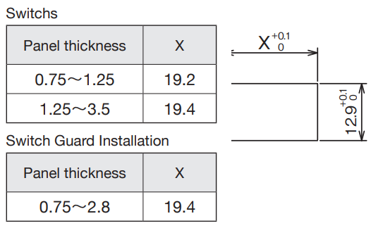
Panel Cut-Out Dimensions
Handling Precautions
1. Soldering Specifications
⑴Manual Soldering
Device : Soldering iron
380 ℃, Max.; 3 seconds, Max.
※The tab terminals cannot be soldered
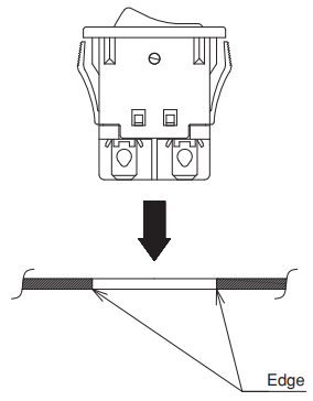
2. Precautions for panel mounting
The edges on the back of the cut-out panel should be squared so that the switch box bites the panel firmly. When the panel is coated, pay attention that the coating will not retain around the edge. Do not reuse the switch that was once mounted on a panel.
List of part numbers
| Part number | Current | Terminal style | Switching function | CAD |
|---|---|---|---|---|
| ★SLE10A | 10 A | Solder Terminal | ON - OFF | |
| ★SLE10A-5 | 10 A | Solder Terminal | ON - OFF | |
| ★SLE10D-5 | 10 A | Solder Terminal | ON - ON | |
| SLE10A2-5 | 10 A | t=0.5 TAB#187 | ON - OFF | |
| ★SLE10D2-5 | 10 A | t=0.5 TAB#187 | ON - ON | |
| ☆SLE10A5-5 | 10 A | t=0.8 TAB#187 | ON - OFF | |
| ★SLE10A-6 | 10 A | Solder Terminal | ON - OFF | |
| SLE10A2-6 | 10 A | t=0.5 TAB#187 | ON - OFF | |
| ★SLE10D2-6 | 10 A | t=0.5 TAB#187 | ON - ON | |
| ★SLE10A5-6 | 10 A | t=0.8 TAB#187 | ON - OFF | |
| ☆SLE10A-7 | 10 A | Solder Terminal | ON-OFF | |
| ★SLE10A2-7 | 10 A | t=0.5 TAB#187 | ON - OFF | |
| ▲SLE10A5-7 | 10 A | t=0.8 TAB#187 | ON - OFF |
Outline Dimensions
(Unit:mm)
Panel Cut-Out Dimensions
Handling Precautions
1. Soldering Specifications
⑴Manual Soldering
Device : Soldering iron
380 ℃, Max.; 3 seconds, Max.
※The tab terminals cannot be soldered
2. Precautions for panel mounting
The edges on the back of the cut-out panel should be squared so that the switch box bites the panel firmly. When the panel is coated, pay attention that the coating will not retain around the edge. Do not reuse the switch that was once mounted on a panel.
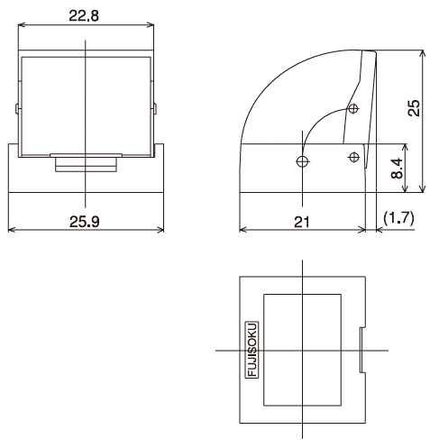
Switch Guard (Dedicated for use of rocker switches)
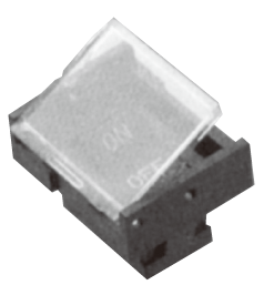
◆Features
Clear visibility and one-touch mounting to save labor
◆Application
Best suited for protection of malfunction of miniature
rocker switches (panel cutout: 19.2 x 12.9)
◆Specifications
Part Name: Switch guard
Part Number: 140007250027
Color: Black( transparent cover)
◆An application switch
●SLE6 ●SL10K ●SLE10 ●SLE210K
※The switch guard cannot be used for the SLE10K series, SLE210K right angle terminal.
Unterlagen
Umweltdaten
- ●Die oben genannten Inhalte können ohne vorherige Ankündigung geändert werden.
Produkte
