


-
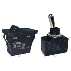
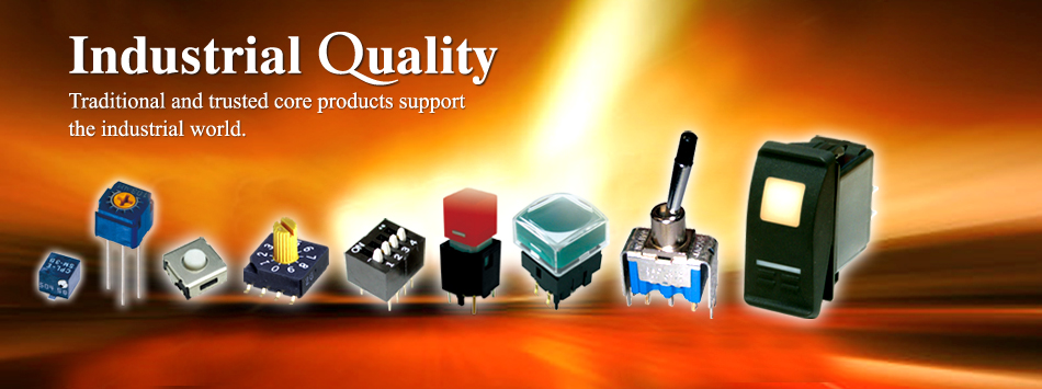
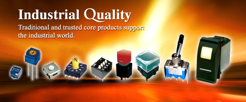
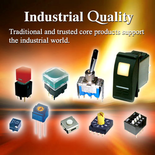
Environmentally Sealed SWs
Ideal for equipment used outdoors Rocker SW & Toggle SW ELW / ETW -
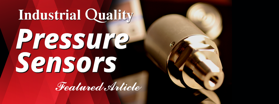
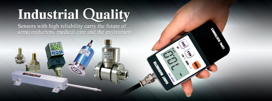
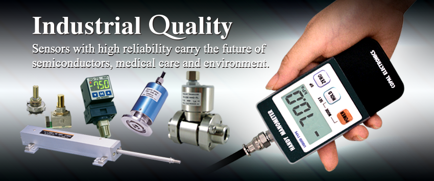
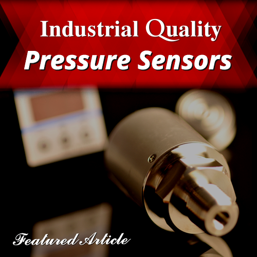
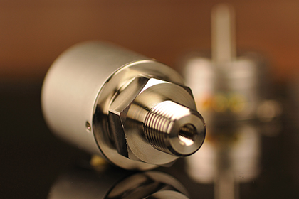
Suitable for high vacuum or
high temp. or high pressure range Thin-film Pressure Sensors Product Lineup -
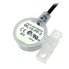
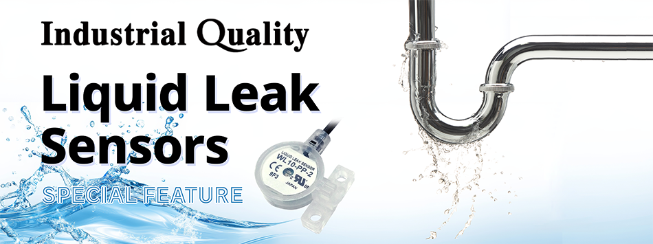
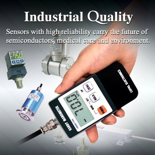
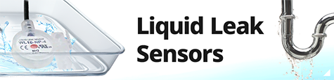
Quick and accurate detection,
Compatible with corrosive liquids Leakage Sensor WL10 -
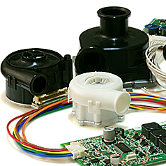
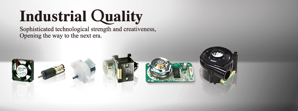
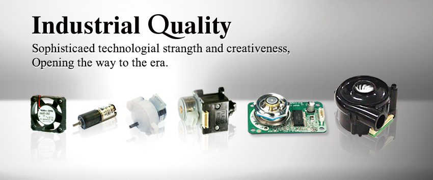
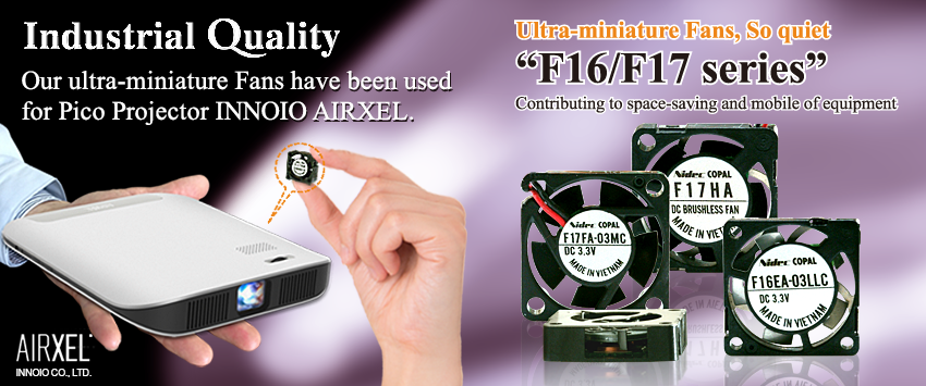
Compact but high power!
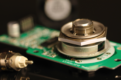
Long life, Low vibration Aerodynamic Bearings Micro Blowers
-
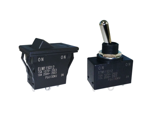
Rocker Switch & Toggle SwitchELW / ETWCompact and high capacity 15 A. Environmentally Sealed SWsSwitches. Ideal for equipment used outdoors.
-
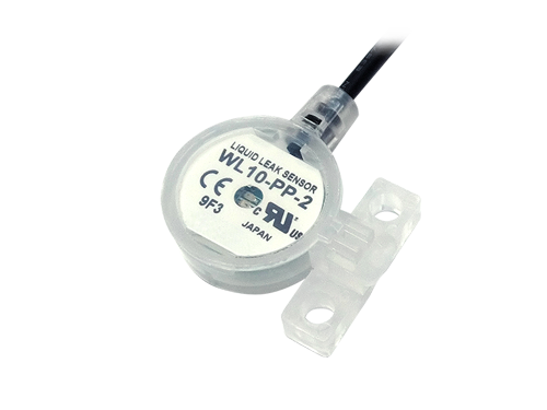
Quick & Accurate DetectionLeakage Sensor WL10Available Compatible with corrosive liquids by PFA-housing. Without reflection control plate or additional Amp.
-
Thin-film Pressure SensorsProduct LineupSuitable for high vacuum or high temperature or high pressure range.
-
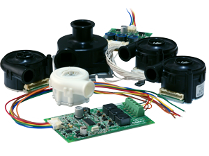
Micro BlowersTF seriesAerodynamic bearings technology realizes long life and low vibration, small size compact but high power.
-
2023/12/28

[New!] Environmentally sealed IP 67 rated ELW Rocker & ETW Toggle switches
-
2023/03/31

Completed the acquisition of all the shares of Midori Precisions Co., Ltd.
-
2023/03/15
Executed a stock transfer agreement on the acquisition of Midori Precisions Co., Ltd.
-
2023/02/01
Notification of Company Name Change (Effective 1 April)
-
2020/06/01
New Product Lineup Announcement:High precision pressure switch "PS97 series" for middle-high pressure
