


Rotary encoders RE30E

-
●To buy this product, please go to the following Online Web stores.


Power supply voltage is for 5~12V, 24V
- With temp. compensation circuit
- With zero index signal
- Power supply voltage is for 5 ~ 12 V, 24 V
- Economy type
- RoHS compliant
PART NUMBER DESIGNATION
| RE30E- | 100- | 2 | 1 | 3- | 1 |
|---|---|---|---|---|---|
|
Series name |
Resolution (P/R)(P/R) 100, 200, 300, 360, 400, 500, 600, 800, 900, 1000, 1024 |
Output phase 2: “A” & “B” |
Output phase “Z” 1: Provided |
Waveform shaping amplifier&Input voltage 3: 5 ~ 12 V 4: 5 ~ 12 V Open collector A: 24 V Open collector |
Output connection 1: Cable wire |
LIST OF PART NUMBERS
| Resolution | Input voltage | CAD | |||
|---|---|---|---|---|---|
| 5 ~ 12 V | 5 ~ 12 V Open collector | 24 V | 24 V Open collector | ||
| 100 (P/R) | RE30E-100-213-1 | ➡RE30E-100-214-1 | ➡RE30E-100-218-1 | ➡RE30E-100-21A-1 |
|
| 200 (P/R) | RE30E-200-213-1 | ➡RE30E-200-214-1 | ➡RE30E-200-218-1 | ➡RE30E-200-21A-1 | |
| 300 (P/R) | RE30E-300-213-1 | ➡RE30E-300-214-1 | ➡RE30E-300-218-1 | ➡RE30E-300-21A-1 | |
| 360 (P/R) | RE30E-360-213-1 | ➡RE30E-360-214-1 | ➡RE30E-360-218-1 | ➡RE30E-360-21A-1 | |
| 400 (P/R) | RE30E-400-213-1 | ➡RE30E-400-214-1 | ➡RE30E-400-218-1 | ➡RE30E-400-21A-1 | |
| 500 (P/R) | RE30E-500-213-1 | ➡RE30E-500-214-1 | ➡RE30E-500-218-1 | ➡RE30E-500-21A-1 | |
| 600 (P/R) | RE30E-600-213-1 | ➡RE30E-600-214-1 | ➡RE30E-600-218-1 | ➡RE30E-600-21A-1 | |
| 800 (P/R) | RE30E-800-213-1 | ➡RE30E-800-214-1 | ➡RE30E-800-218-1 | ➡RE30E-800-21A-1 | |
| 900 (P/R) | RE30E-900-213-1 | ➡RE30E-900-214-1 | ➡RE30E-900-218-1 | ➡RE30E-900-21A-1 | |
| 1000 (P/R) | RE30E-1000-213-1 | ➡RE30E-1000-214-1 | ➡RE30E-1000-218-1 | ➡RE30E-1000-21A-1 | |
| 1024 (P/R) | RE30E-1024-213-1 | ➡RE30E-1024-214-1 | ➡RE30E-1024-218-1 | ➡RE30E-1024-21A-1 | |
The products indicated by ➡mark are manufactured upon receipt of order basis.
Electrical characteristics
| Input voltage | 5 ~ 12 VDC ± 10 % | 24 VDC ± 10 % | |
|---|---|---|---|
| Input current | 50 mA maximum | ||
| Output wave form | Square wave | ||
| Output phases | A, B, Z | ||
| Resolution (P/R) | 100, 200, 300, 360, 400, 500,600, 800, 900, 1000, 1024 | ||
| Phase difference of outputs A & B | 90° ± 45° | ||
| Maximum frequencys response | 10 kHz (100 P/R), 20 kHz (200 P/R),25 kHz (300 ~ 500 P/R), 60 kHz (600 P/R),80 kHz (800 P/R), 90 kHz (900 P/R) | ||
| Output signal | “1 (High)” | (Vcc - 1) V min. | (Vcc - 2) V min. |
| “0 (Low)” | + 0.5 V max. | + 1.0 V max. | |
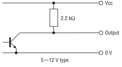
| Output impedance | 2.2 kΩ | ||
| Light source | LED | ||
Mechanical characteristics
| Starting torque | 0.29 mN·m {3 gf·cm} maximum | |
|---|---|---|
| Inertia | 2 g·cm2 maximum | |
| Shaft loading (When mounting) | Radial | 19.6 N {2 kgf} maximum |
| Axial | 9.81 N {1 kgf} maximum | |
| Net weight | Approx. 70 g | |
Environmental characteristics
| Operating temp. range | 0 ~ 70 °C |
|---|---|
| Storage temp. range | - 20 ~ 80 °C |
| Protection grade | IP40 |
RELIABILITY TEST
⦿The output wave form shall satisfy the STANDARD SPECIFICATIONS after the following tests.
| Test item | Test conditions | ||
|---|---|---|---|
| Vibration | Power OFF | Amplitude : 1.52 mm or 98.1 m/s2 (10 G) whichever is smaller. 10 ~ 500 Hz excursion 0.25 h/cycle, 8 cycles each for X, Y, Z, directions. |
|
| Shock | Power OFF | 3 times each in 6 directions (X, Y, Z) at 490 m/s² (50 G), 11 ms. | |
| High temperature exposure | Power OFF | 80 °C 96 h | (To be measured after leaving samples for 1 h at normal temperature and humidity after the test.) |
| Power ON | 70 °C 96 h | ||
| Low temperature exposure | Power OFF |
- 20 °C 96 h |
|
| Power ON | 0 °C 96 h | ||
| Humidity | Power OFF | 40 °C Relative humidity 90 ~ 95 % 96 h (To be measured after wiping out moisture and leaving samples for 1 h at normal temperature and humidity after the test.) |
|
| Thermal shock | Power OFF | To be done 10 cycles with the following condition (To be measured after leaving samples for 1 h at normal temperature and humidity after the test.) 80 °C 1 h、- 20 °C 1 h |
|
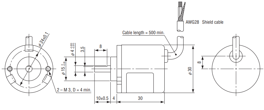
OUTLINE DIMENSIONS
Unless otherwise specified, tolerance: ± 0.4 (Unit: mm)
ELECTRICAL WIRING
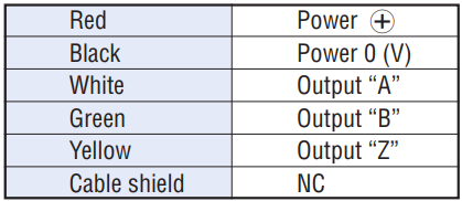
OUTPUT
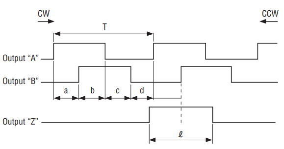 a, b, c, d = 1/4±T1/8T
 ℓ= T±3/4T
The “Z” phase, however, includes no more than two “B” phase startups (CW rotation)
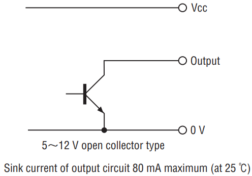
OUTPUT CIRCUIT
⦿5〜12 V type
⦿5〜12 V open collector type
Documents
- ●The above contents and descriptions are subject to change without notice.
