


Lever&rocker switch 8V-M

-
●To buy this product, please contact Sales Reps, Distributors.
Small Lever & Rocker Switches for PC Board
FeaturesFeatures
-
The 8V-M Small Lever & Rocker Switches for PC Board are designed for use with printed circuit boards.
-
It is easy to directly mount the switch on the PC board and the switch is provided with supporting bracket for stabilized switch
mounting. -
Levers and rockers are available in four matted colors that give an elegant atmosphere.
-
Choose the suitable one for the panel design.
- PCB mounting
Specifications
| Rating Max. | 125 VAC 6 A / 250 VAC 3 A / 30 VDC 4 A |
|---|---|
| Initial contact resistance | 10 mΩ Max.(2 ~ 4 VDC 1 A) |
| Initial dielectric strength | 1500 VAC 1 minute |
| Initial insulation resistance | 1000 MΩ Min. (500 VDC) |
| Electrical life | Alternate type: 50,000 cycles Momentary type: 25,000 cycles |
| Operating temperature range | - 30 ~ + 85 ℃ |
| Strage temperature range | - 40 ~ + 85 ℃ |
Part Number Designation
| 8 | V | 1 | 01 | 2 | - M | - Z | |
|---|---|---|---|---|---|---|---|
|
Series |
Installation V: For PCB |
No. of poles 1: 1 pole 2: 2 poles |
SW function 01: ON - ON 06: ON - (ON) |
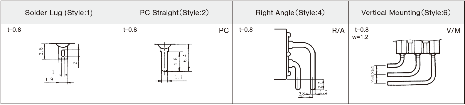
Terminal style 2: PC straight |
Contact material / Plating Blank: Bs+Ag or Cu+Ag / Silver plated / Silver plated Bs=Brass, Ag=Silver, |
Actuator shape M: Small lever / |
◆Terminal style
List of Part Numbers
| Part No. | Circuit | Switching function | UL | CSA | CAD |
|---|---|---|---|---|---|
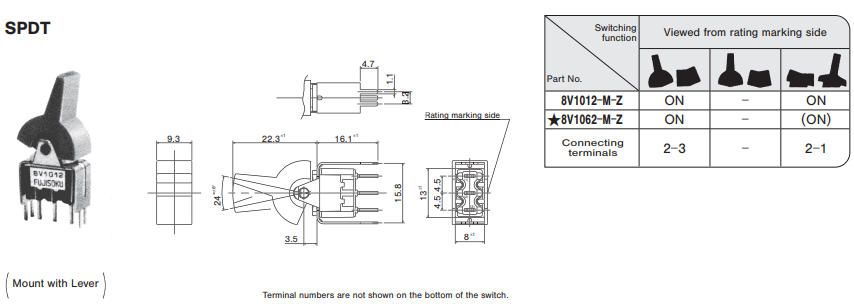
| Part No.:8V1012-M-Z | SPDT | ON - ON | 〇 | 〇 | |
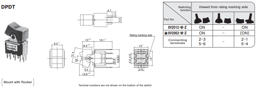
| Part No.:8V2012-M-Z | DPDT | ON - ON | 〇 | 〇 | |
| Part No.:8V1062-M-Z★ | DPDT | ON - ON | 〇 | 〇 | |
| Part No.:8V2062-M-Z★ | DPDT | ON - (ON) | ― | ― |
★: Made to order products
※
When the UL recognized or CSA certified products are required, specify that effect when placing the order. The products will be delivered with the UL or CSA marking.
UL recognized: File No. E43275 /
CSA certified: File No. LR38341
CSA certified: File No. LR38341
Standard Accessories
| Actuator | Part No. | Color | Outline dimensions |
|---|---|---|---|
| Lever | 140000050427 | White | 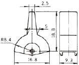 |
| 140000050428 | Red | ||
| 140000050450 | Gray | ||
| Rocker | 140000480509 | White | 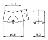 |
| 140000480510 | Red | ||
| 140000480511 | Black |
※
Specify either one of lever or rocker in part number when placing an order.
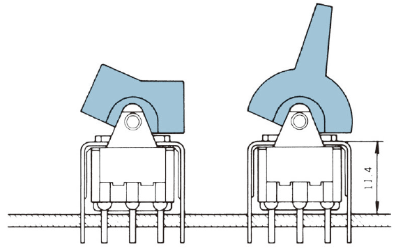
Outline Dimensions
(Unit:mm)
Lever or Rocker Installation Procedure
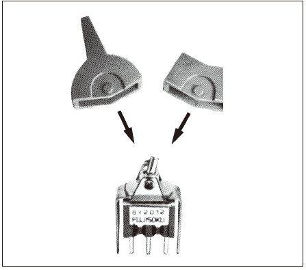
Insert the lever or the rocker provided onto the switch from the above.
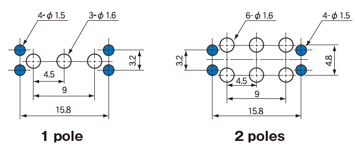
PC Hole Layouts
Handling Precautions
◆Soldering Specifications
- Manual Soldering
Device : Soldering iron
①420 ℃, Max.; 3 sec., Max. - Auto Soldering
②275 ℃ ± 10℃, Max.; 5 seconds, Max.
Note that the above-stated soldering conditions should be applied to the PC terminal type only.
◆Flux Cleaning
- For the solvent, use the fluorine- or alcohol-based solvent.
Solvent: Fluorine or Alcohol type - Since the 8 Switch Series switches are not waterproof-structured, if the PC board is to be cleaned, clean the soldering surface of substrate with a brush so that the switch is not exposed to the cleaning solution.
◆Mounting
- Do not bend the terminals before mounting the switch on the PC board.
- After mounting the switch, do not place the device in such a way that the device weight will be applied on the knob of the switch.
- To fix the PC terminal type, solder it on the PC board after fixing the switch body on the panel with the screw.
Documents
Environmental files
- ●The above contents and descriptions are subject to change without notice.
