


Slide switch MFS

-
●To buy this product, please go to the following Online Web stores.


Common Specifications
- Initial contact resistance
Measured at 1.5mA 200 μVAC 1kHz - Dilectric strength
Measurement at 500 VAC. - Insulation Resistance
Measured at 500 VDC - Operating temperature range
- 10 ℃ ~ + 70 ℃
Part Number Designation
| MFS | 101 | D- | 6 - | Z |
|---|---|---|---|---|
|
Series code |
Number of poles 101: 1-pole |
Switching function D:1-pole or 3-poles/ON ー ON |
Registration number |
※Please refer to the model list below for the complete lineup.
List of Part Numbers
※
A part number indicated with a gray-back in the list below is discontinued with an order deadline of July. 13, 2026.
| Part No. | Rating (Resistive load) | Initial contact resistance | Insulation resistance | Operating force | Switch timing | CAD |
|---|---|---|---|---|---|---|
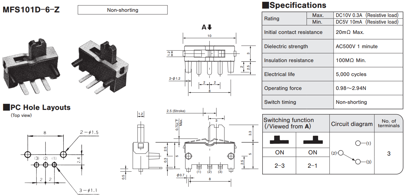
| MFS101D-6-Z |
Max.
10 VDC 0.3 A,
Min. 5 VDC 10 mA
|
20 mΩ Max. | 100 MΩ min. | 0.98 ~ 2.94 N | Non-shorting | |
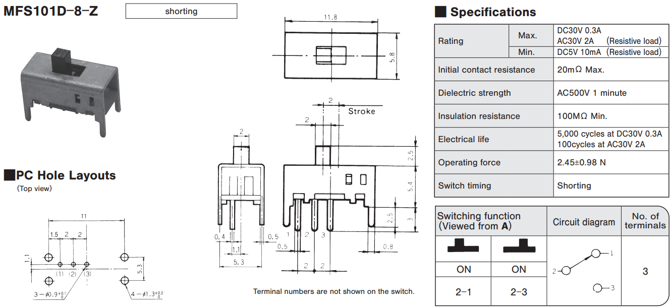
| MFS101D-8-Z |
Max.
30 VDC 0.3 A
/ 30 VAC 2 A, Min. 5 VDC 10 mA
|
20 mΩ Max. | 100 MΩ min. | 2.45 ±0.98 N | Shorting | |
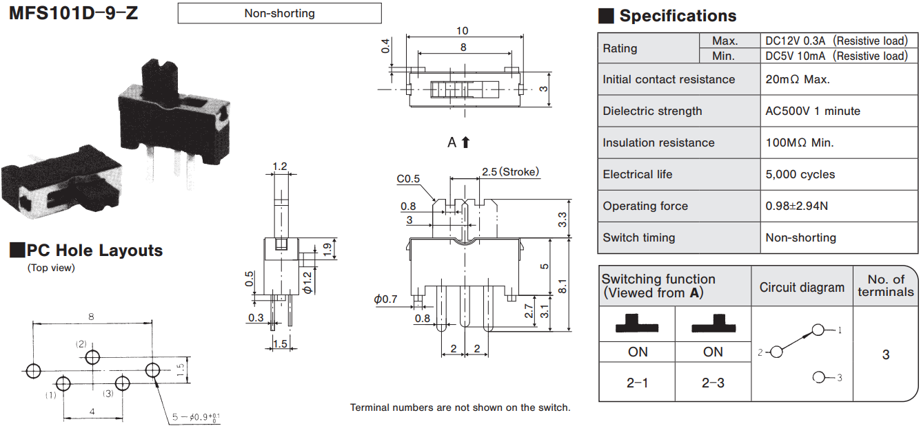
| MFS101D-9-Z |
Max.
12 VDC 0.3 A,
Min. 5 VDC 10 mA
|
20 mΩ Max. | 100 MΩ min. | 0.98 ±2.94 N | Non-shorting | |
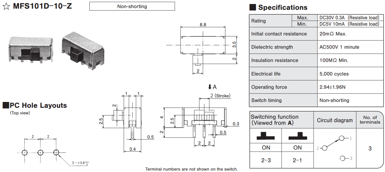
| MFS101D-10-Z☆ |
Max.
30 VDC 0.3 A,
Min. 5 VDC 10 mA
|
20 mΩ Max. | 100 MΩ min. | 2.94 ±1.96 N | Non-shorting | |
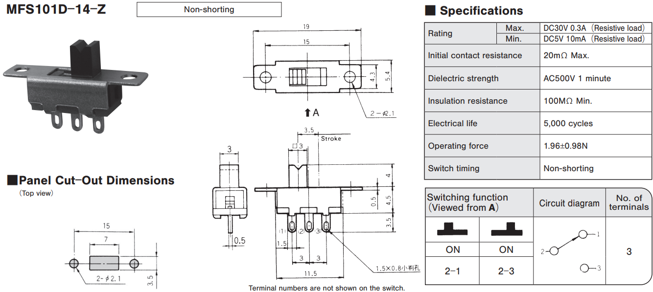
| MFS101D-14-Z |
Max.
30 VDC 0.3 A,
Min. 5 VDC 10 mA
|
50 mΩ Max. | 100 MΩ min. | 1.96 ±0.98 N | Non-shorting | |
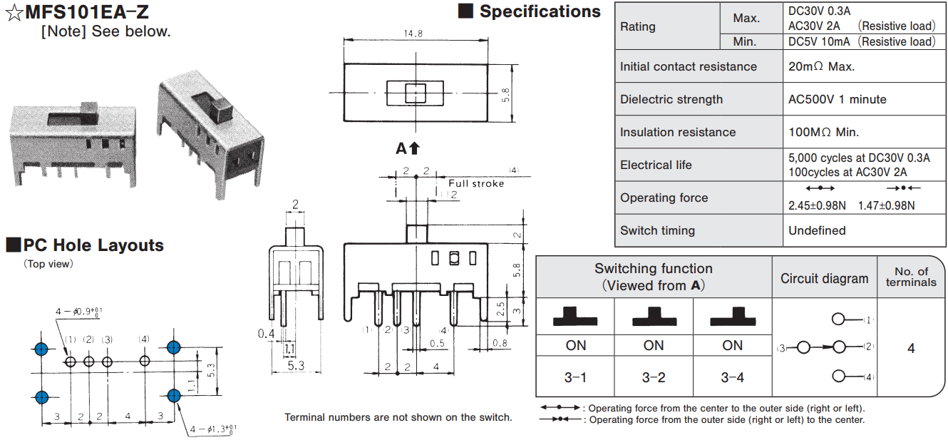
| MFS101EA-Z☆ |
Max.
30 VDC 0.3 A
/ 30 VAC 2 A, Min. 5 VDC 10 mA
|
50 mΩ Max. | 100 MΩ min. | 2.45 ±0.98 N / 1.47 ±0.98 N |
Undefined | |
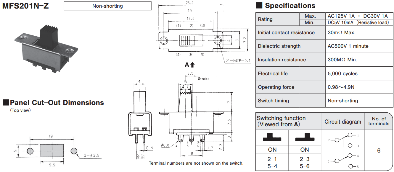
| MFS201N-Z |
Max.
125 VAC 1A
/ 30 VDC 1 A, Min. 5 VDC 10 mA
|
30 mΩ Max. | 100 MΩ min. | 0.98 ~ 4.9 N | Non-shorting | |
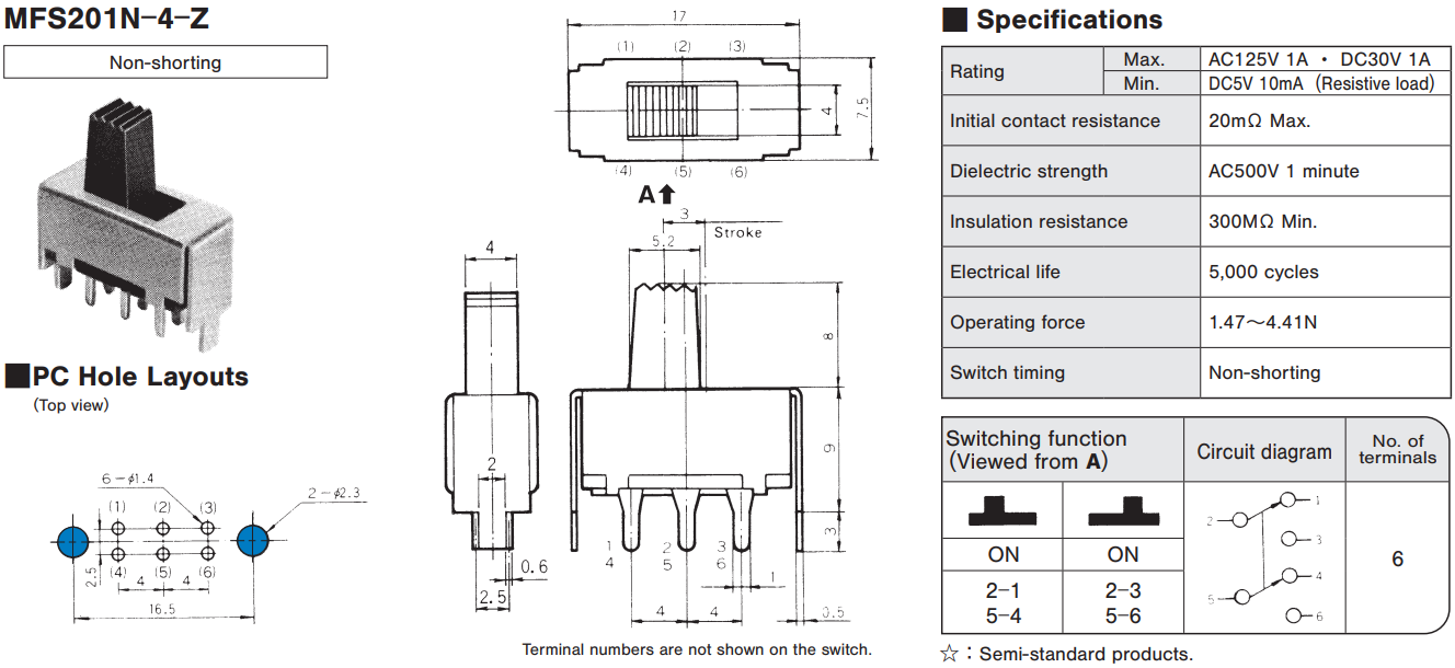
| MFS201N-4-Z |
Max.
125 VAC 1 A
/ 30 VDC 1 A, Min. 5 VDC 10 mA
|
20 mΩ Max. | 300 MΩ min. | 1.47 ~ 4.41 N | Non-shorting | |
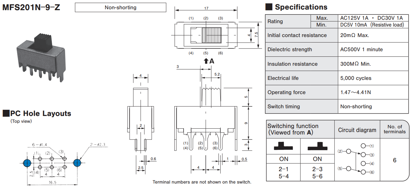
| MFS201N-9-Z |
Max.
125 VAC 1 A
/ 30 VDC 1 A, Min. 5 VDC 10 mA
|
20 mΩ Max. | 300 MΩ min. | 1.47 ~ 4.41 N | Non-shorting | |
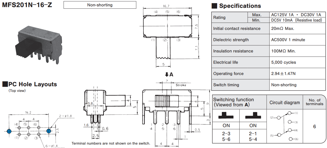
| MFS201N-16-Z |
Max.
125 VAC 1 A
/ 30 VDC 1 A, Min. 5 VDC 10 mA
|
20 mΩ Max. | 100 MΩ min. | 2.94 ±1.47 N | Non-shorting | |
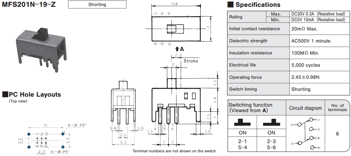
| MFS201N-19-Z |
Max.
30 VDC 0.3 A,
Min. 5 VDC 10 mA
|
20 mΩ Max. | 100 MΩ min. | 2.45 ±0.98 N | Shorting | |
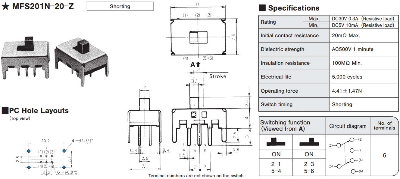
| MFS201N-20-Z★ |
Max.
30 VDC 0.3 A,
Min. 5 VDC 10 mA
|
20 mΩ Max. | 100 MΩ min. | 4.41 ±1.47 N | Shorting | |
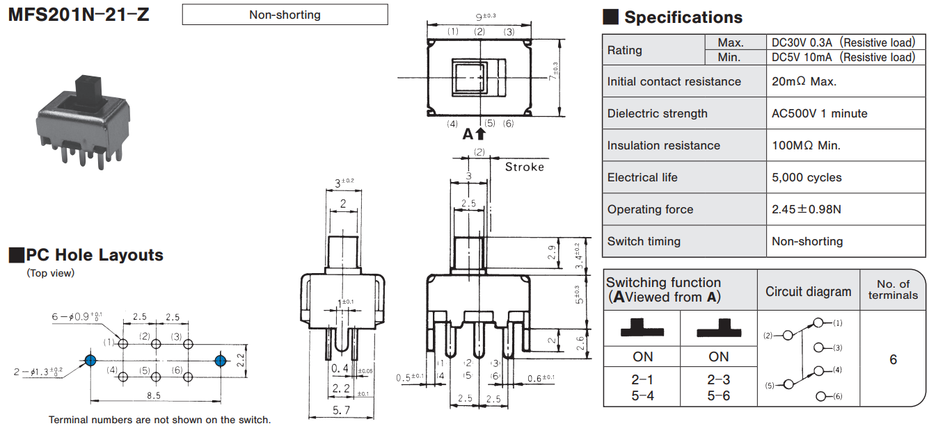
| MFS201N-21-Z |
Max.
30 VDC 0.3 A,
Min. 5 VDC 10 mA
|
20 mΩ Max. | 100 MΩ min. | 2.45 ±0.98 N | Non-shorting | |
| MFS201N-23-Z |
Max.
30 VDC 0.3 A,
Min. 5 VDC 10 mA
|
20 mΩ Max. | 100 MΩ min. | 3.92 ±2.45 N | Non-shorting | |
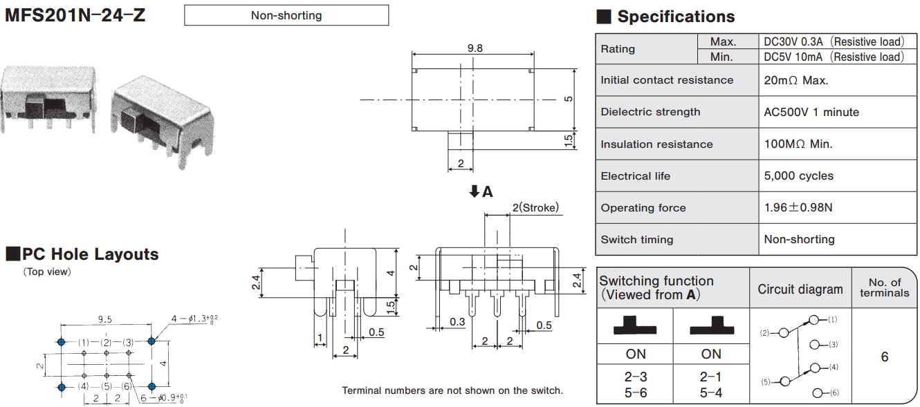
| MFS201N-24-Z |
Max.
30 VDC 0.3 A,
Min. 5 VDC 10 mA
|
20 mΩ Max. | 100 MΩ min. | 1.96 ±0.98 N | Non-shorting | |
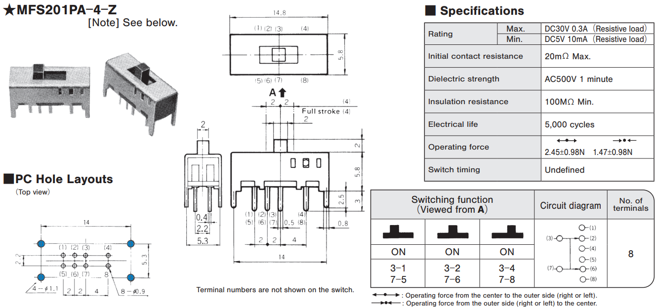
| MFS201PA-4-Z★ |
Max.
30 VDC 0.3 A,
Min. 5 VDC 10 mA
|
20 mΩ Max. | 100 MΩ min. | 2.45 ±0.98 N / 1.47 ±0.98 N |
Undefined | |
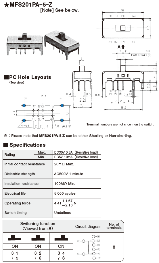
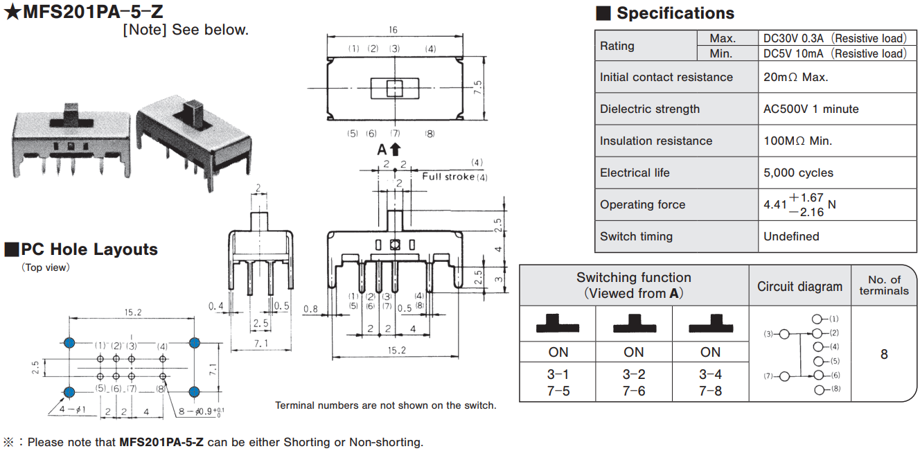
| MFS201PA-5-Z★ |
Max.
30 VDC 0.3 A,
Min. 5 VDC 10 mA
|
20 mΩ Max. | 100 MΩ min. | 4.41 +1.67 N / 4.41 -2.16 N |
Undefined | |
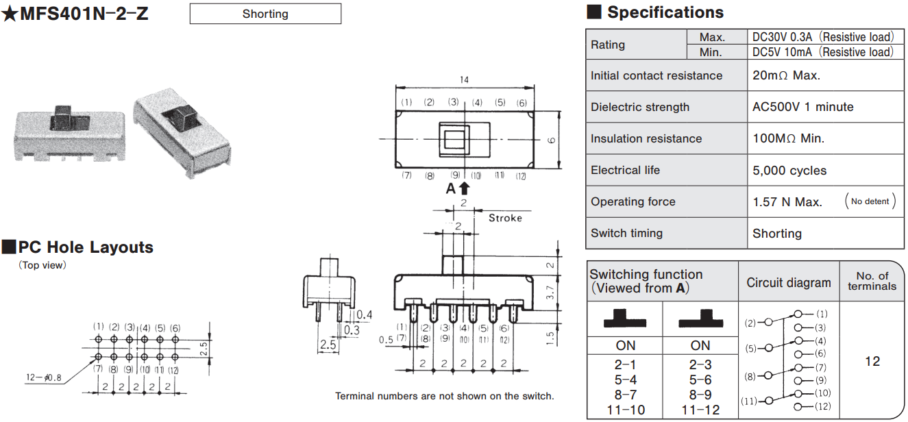
| MFS401N-2-Z★ |
Max.
30 VDC 0.3 A,
Min. 5 VDC 10 mA
|
20 mΩ Max. | 100 MΩ min. | 0.98 N Max. (No detent) | Shorting |
☆: Semi-standard products / ★: Made to order products
Outline Dimensions
(Unit:mm)
Soldering
- Manual Soldering Device : Soldering iron Please refer to “MFS Series Heat-resistant Table” shown below.
- Auto Soldering MFS series are not compatible with auto soldering. Soldering should be done manually.
- When soldering two or more terminals to the common land, use solder resist to solder them independently
◆MFS series heat-resistant table
| Resin board | MFS101D-6-Z | 270 ℃ MAX. 3sec MAX. |
|---|---|---|
| MFS101D-9-Z | ||
| MFS101D-11-Z | ||
| Phenol board | MFS101D-8-Z | 360 ℃ MAX. 3sec MAX. |
| MFS201N-19-Z | ||
| MFS201N-20-Z | ||
| MFS101D-10-Z | ||
| MFS101D-14-Z | ||
| MFS201N-Z | ||
| MFS201N-4-Z | ||
| MFS201N-9-Z | ||
| MFS201N-16-Z | ||
| MFS201N-21-Z | ||
| MFS201N-23-Z | ||
| MFS201N-24-Z | ||
| MFS201PA-4-Z | ||
| MFS101EA-Z | ||
| MFS201PA-5-Z | ||
| MFS401N-2-Z |
Flux Cleaning
- Solvent: Fluorine or Alcohol type.
- MSF Series are not process sealed. If the PC board is to be cleaned, clean the soldering surface of substrate with a brush so that the switch is not exposed to the cleaning solution.
Frequency of Switch Use
If the switch is not likely to be operated frequently (e.g. two or three operations a year) in the dry circuit area, a sulfide film is likely to be formed on the contacts, resulting in contact failure. If this is the case, goldplated products are recommended. Please contact your local NIDEC COMPONENTS sales representative.
Packaging Specifications

Documents
Environmental files
- ●The above contents and descriptions are subject to change without notice.
