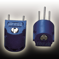
Trimmer potentiometer TM-7
-

TM-7
-

TM-7
- ●To make a purchase, contact Distributors, or use e-commerce below.
SALES CHANNEL ;Check our Distributors.- SALES CHANNELClick here to check our Distributors.


3 turns Cermet Trimmers
FeaturesFeatures
- Fine setting is possible
- Extremely small backlash (In house comparison)
- In this series, material data sheets ideal for REACH-SVHC
surveys etc. can be downloaded in chemSHERPA-AI format. - Download chemSHERPA-AI from the list of P/N below
Electrical Characteristics
| Power ratings | 0.5 W (70 °C) 0 W (120 °C) |
|---|---|
| Nominal resistance range | 50 Ω ~ 2 MΩ |
| Resistance tolerance | ± 10 % |
| Resistance law | Linear law(B) |
| Maximum input voltage | DC300 V or power rating, whichever is smaller |
| Maximum wiper current | 100 mA or power rating, whichever is smaller |
| Effective electrical turn | 2.5 turns |
| End resistance | 1 % or 2 Ω , whichever is greater |
| C.R.V. | 1 % or 3 Ω , whichever is greater |
| Operating temp. range | −55 ~ 120 °C |
| Temp. coefficient | ± 100 10-6/°C maximum |
| Insulation resistance | 1000 MΩ minimum (DC500 V) |
| Dielectric strength | AC900 V, 60 s |
| Net weight | Approx. 0.50 g (TM-7EP, EW) Approx. 0.69 g (TM-7ES, EX) |
Mechanical Characteristics
| Mechanical turn | 3 turns |
|---|---|
| Operating torque | 20 mN·m {204 gf·cm} maximum |
| Mechanical stop | Clutch action |
| Rotational life | 200 cycles ΔR/R ≦ ± (2 Ω +3 %) |
| Terminal strength | 10 N {1.02 kgf} minimum(Tensile strength) |
| Thrust to shaft | 10 N {1.02 kgf} minimum |
| Solderability | 245 ± 3 °C, 2 ~ 3 s |
{ }:Reference only
Environmental Characteristics
| Test item | Test conditions | Specifications |
|---|---|---|
| Shock | 981 m/s2, 6 ms 6 directions for 3 times each | [ΔR/R ≦ 1 %] [S.S. ≦ 1 %] |
| Thermal shock | −65 ~ 125 °C(0.5 h), 5 cycles | [ΔR/R ≦ 1 %] [S.S. ≦ 1 %] |
| Humidity | −10 ~ 65 °C ( Relative humidity 80 ~ 98 %),10 cycles, 240 h | [ΔR/R ≦ 2 %] |
| Vibration | Amplitude 1.52 mm or Acceleration 196 m/s2, 10 ~ 2000 Hz, 3 directions, 12 times each |
[ΔR/R ≦ 1 %] [S.S. ≦ 1 %] |
| Load life | 70 °C, 0.5 W, 1000 h | [ΔR/R ≦ 3 %] [S.S. ≦ 1 %] |
| Low temp. operation | −55 °C, 2 h | [ΔR/R ≦ 2 %] [S.S. ≦ 2 %] |
| High temp. exposure | 120 °C, 250 h | [ΔR/R ≦ 3 %] [S.S. ≦ 2 %] |
| Immersion seal | 85 °C, 60 s | No leaks (No continuous bubbles) |
| Soldering heat | Flow soldering :260 ± 3 °C, 5 ~ 6 s, two times maximum Manual soldering : 380 ± 10 °C, 3 ~ 4 s |
[ΔR/R ≦ 1 %] |
Δ R/R:Change in total resistance S.S. :Setting stability
Maximum Input Ratings
| Nominal resistance values (Ω) | Resistance code | Maximum input voltage(V) | Maximum wiper current(mA) |
|---|---|---|---|
| 50 | 500 | 5.00 | 100 |
| 100 | 101 | 7.07 | 70.7 |
| 200 | 201 | 10.0 | 50.0 |
| 500 | 501 | 15.8 | 31.6 |
| 1k | 102 | 22.4 | 22.4 |
| 2k | 202 | 31.6 | 15.8 |
| 5k | 502 | 50.0 | 10.0 |
| 10k | 103 | 70.7 | 7.07 |
| 20k | 203 | 100 | 5.00 |
| 50k | 503 | 158 | 3.16 |
| 100k | 104 | 224 | 2.24 |
| 200k | 204 | 300 | 1.50 |
| 500k | 504 | 300 | 0.60 |
| 1M | 105 | 300 | 0.30 |
| 2M | 205 | 300 | 0.15 |
Part Number Designation
| TM-7 | E | P | 50 kΩ (503) |
|---|---|---|---|
|
Series |
Terminal pin E:
Sn (Lead-free)
|
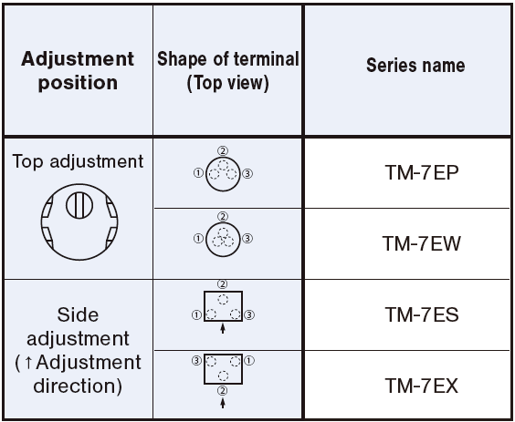
Terminal shape (Adjust Pos.)※1 P:
W: S: X: Through hole (Top adjustment)
Through hole (Top adjustment) Through hole (Side adjustment) Through hole (Side adjustment) |
Resistance value (Resistance code) |
-
※1)For the details on each product shape, refer to the following table and Outline Dimensions.

| Nominal resistance values | 50 Ω, 100 Ω, 200 Ω, 500 Ω, 1 kΩ, 2 kΩ, 5 kΩ, 10 kΩ, 20 kΩ, 50 kΩ, 100 kΩ, 200 kΩ, 500 kΩ, 1 MΩ, 2 MΩ |
|---|
When ordering, please be sure to include the above nominal resistance value at the end of the part number in the table list below. For resistance code, please refer to the Maximum Input Ratings table in the previous section.
List of Part Numbers
CAD and chemSHERPA-AI (a material data sheet ideal for REACH surveys, etc. / version: 2.10.00 or 2.09.00 available) can be downloaded from the button for each P/N in the table below. *Need to log in to download.
| Part No. | Product shape | Form of packaging | Pieces in package | Material data | CAD | |||||||
|---|---|---|---|---|---|---|---|---|---|---|---|---|
| TM-7EP | Top adjustment | Through hole | 50 pcs./pack |
Downloadable chemSHERPA-AI files by selecting the latest ver. 2.10.00 or the previous ver. 2.09.00 from the following buttons. [Need to log in to download]
*
You can download the chemSHERPA Data(AI) Entry Support Tool for articles V2R1.00.1 (compatible with up to the latest data sheet ver.2.10) from here.
|
||||||||
| TM-7EW | Top adjustment | Through hole | 50 pcs./pack |
Downloadable chemSHERPA-AI files by selecting the latest ver. 2.10.00 or the previous ver. 2.09.00 from the following buttons. [Need to log in to download]
*
You can download the chemSHERPA Data(AI) Entry Support Tool for articles V2R1.00.1 (compatible with up to the latest data sheet ver.2.10) from here.
|
||||||||
| TM-7ES | Side adjustment | Through hole | 50 pcs./pack |
Downloadable chemSHERPA-AI files by selecting the latest ver. 2.10.00 or the previous ver. 2.09.00 from the following buttons. [Need to log in to download]
*
You can download the chemSHERPA Data(AI) Entry Support Tool for articles V2R1.00.1 (compatible with up to the latest data sheet ver.2.10) from here.
|
||||||||
| TM-7EX | Side adjustment | Through hole | 50 pcs./pack |
Downloadable chemSHERPA-AI files by selecting the latest ver. 2.10.00 or the previous ver. 2.09.00 from the following buttons. [Need to log in to download]
*
You can download the chemSHERPA Data(AI) Entry Support Tool for articles V2R1.00.1 (compatible with up to the latest data sheet ver.2.10) from here.
|
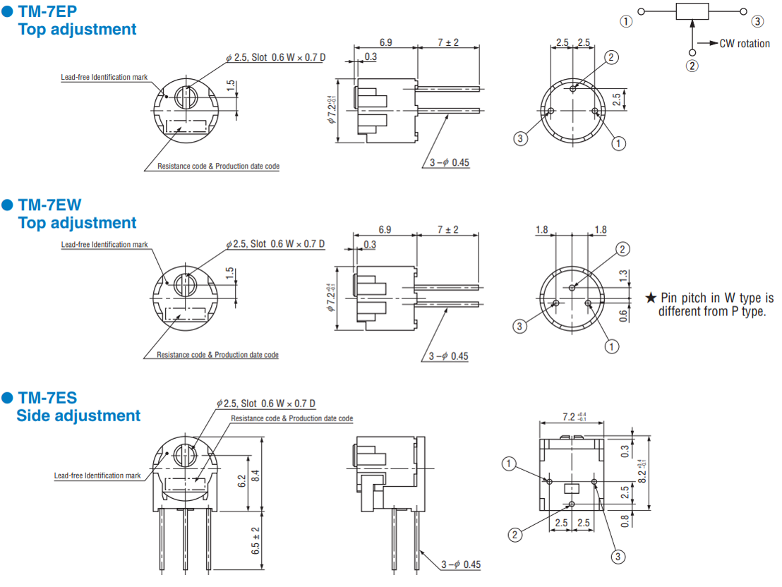
Outline Dimensions
Unless otherwise specified, tolerance: ± 0.3 (Unit: mm)


Documents
- ●The above contents and descriptions are subject to change without notice.


