


For LiDAR scanning solution Polygon Mirrors Special Feature Vol.3
For LiDAR scanning solution Polygon Mirrors Special Feature Vol.3
- Chapter 10
- Recommend Mirror Thickness ReductionThinning (2)
-(2) Technological Approach-

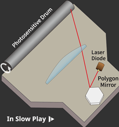
Here is an animation on the right illustrating laser scanning with a polygon mirror within the laser printer head.
The thickness of the polygon mirrors significantly affects the productivity of applications utilizing laser scanning. Reducing of the mirror thickness is highly effective for reducing production costs, as proven in industrial equipment that has achieved remarkable advancements in mirror thinning through years of technological innovation, optical system improvements have played a significant role specifically. For your reference, we'll guide you through the process of gradual mirror thinning along with the evolution of optical technologies in laser printers.
Please note that the figures included in the explanations below all depict the structure of the laser printer head as viewed from an overhead angle. They are considerably distorted from reality to make it easier to understand the technical points. Kindly keep this in mind.
1. Post-objective optical system

2. Pre-objective optical system

3. Compensating for dynamic error

4. Wide angle scanning using an aspherical lens

Advocating Polygon Mirror thickness reduction for LiDAR
As our company boasts a world-leading supply record for thin polygon mirrors used in industrial applications, similar achievements can be applied to LiDAR. Taking the example of the technological evolution in industrial mentioned above as reference, we strongly encourage considering the polygon mirror thickness reduction for LiDAR applications as well.
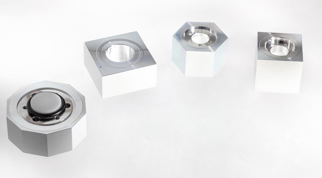
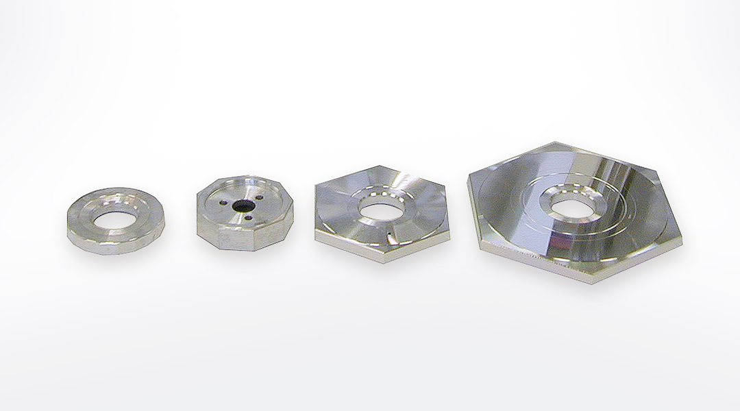
Polygon mirrors for Industrial
ー Fin ー
