


Slide switch AS

-
●To buy this product, please go to the following Online Web stores.


Hyper-miniature Slide Switchess
-
High Contact Reliability
Twin-contact clip mechanism for high contact reliability. -
Gold-plated contacts suitable for low current applications
For PC board mounting -
Improved operability
The independent detent structure provides a light operating touch
Specifications
| Rating 0.4VA AC/DC |
Voltage range : 20 mV ~ 60 V |
|---|---|
| Rating Max. | 60 VAC / VDC 50 mA |
| Rating Min. | DC 20 mVAC / VDC 1μA |
| Initial contact resistance | 50 mΩ max.(1.5 mA 200 μVAC) |
| Dielectric strength | 250 VAC 1 minute |
| Initial insulation resistance | 500 MΩ min. (500 VDC) |
| Electrical life | 10,000 cycles at max. rating 50,000 cycles at min. rating or 0.4 VA |
| Operating force | 0.69 ~ 4.9 N |
| Operating temperature range | - 20 ℃ ~ + 85 ℃ |
| Storage temperature range | - 40 ℃ ~ + 85 ℃ |
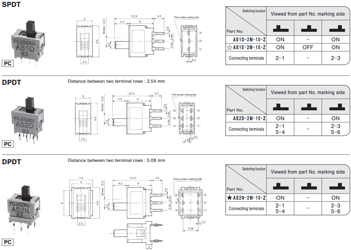
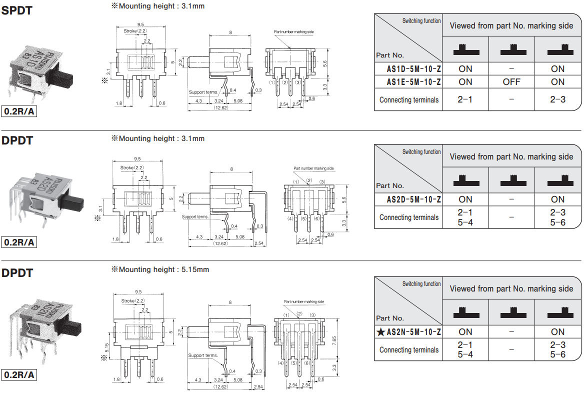
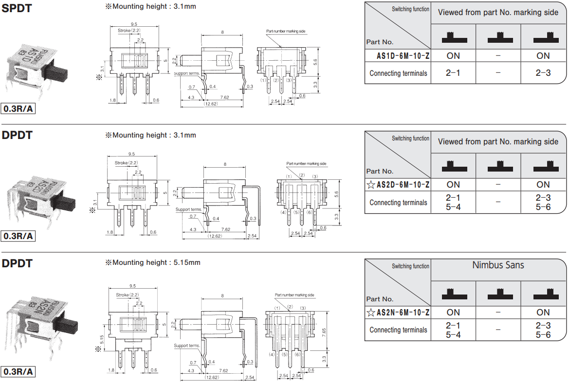
Part Number Designation
| A | S | 1 | D - | 2 | M | - 10 - Z |
|---|---|---|---|---|---|---|
|
Series |
Actuator type S: Slide |
No. of poles 1: 1 pole 2: 2 poles |
SW function D: On-On Terminal rows pitch: 0.1" N: On-On Terminal rows pitch: 0.2" E: On-Off-On Terminal rows pitch: 0.1" |
Terminals 2: PC straight 5: R/A 0.2" pitch 6: R/A 0.3" pitch |
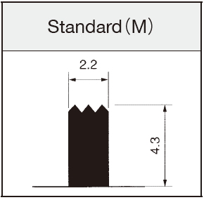
Actuator shape M: Standard |
Clip mechanism |
List of Part Numbers
| Part No. | Circuit | Terminals | SW function | CAD |
|---|---|---|---|---|
| Part No.:AS1D-2M-10-Z | SPDT | PC straight | ON - ON | |
| Part No.:AS1E-2M-10-Z☆ | SPDT | PC straight | ON - OFF - ON | |
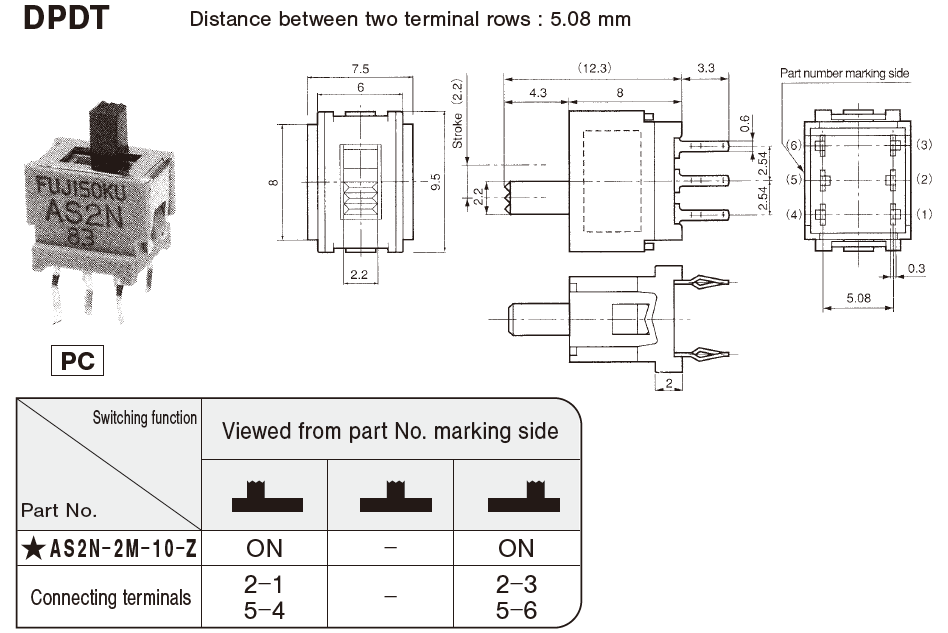
| Part No.:AS2D-2M-10-Z | DPDT | PC straight | ON - ON | |
| Part No.:AS2N-2M-10-Z★ | DPDT | PC straight | ON - ON | |
| Part No.:AS1D-5M-10-Z | SPDT | R/A 0.2 inch pitch | ON - ON | |
| Part No.:AS1E-5M-10-Z | SPDT | R/A 0.2 inch pitch | ON - OFF - ON | |
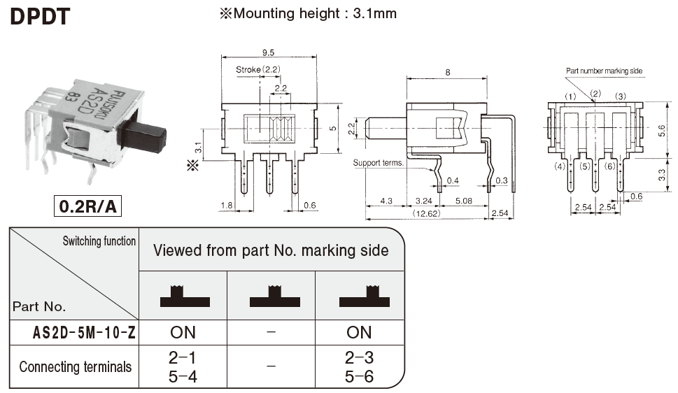
| Part No.:AS2D-5M-10-Z | DPDT | R/A 0.2 inch pitch | ON - ON | |
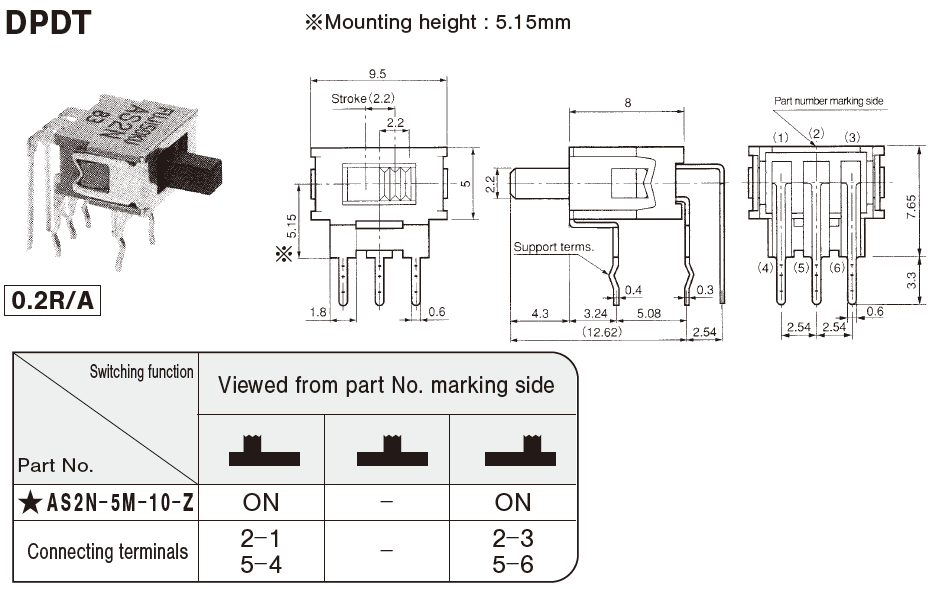
| Part No.:AS2N-5M-10-Z★ | DPDT | R/A 0.2 inch pitch | ON - ON | |
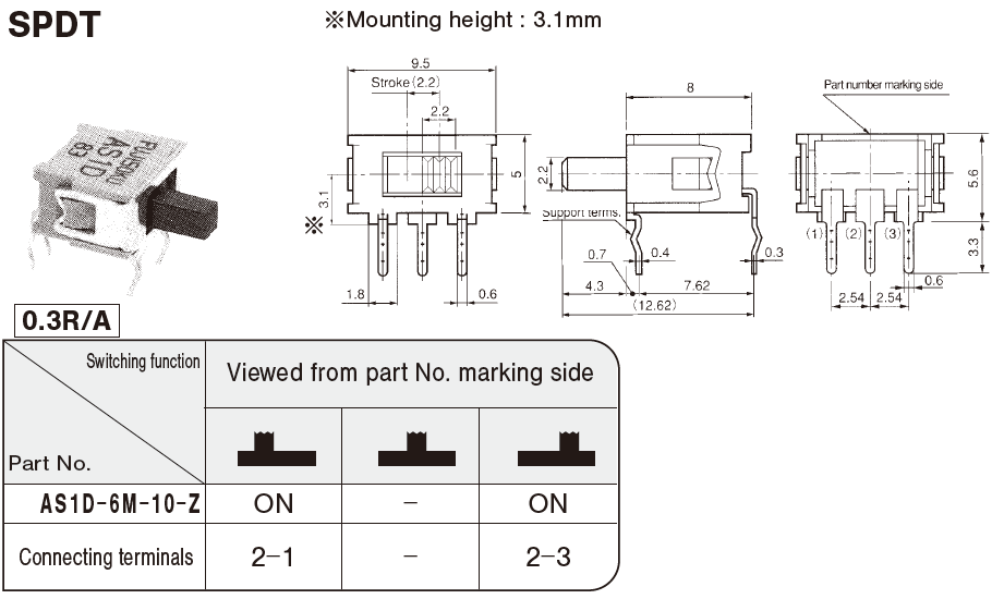
| Part No.:AS1D-6M-10-Z | SPDT | R/A 0.3 inch pitch | ON - ON | |
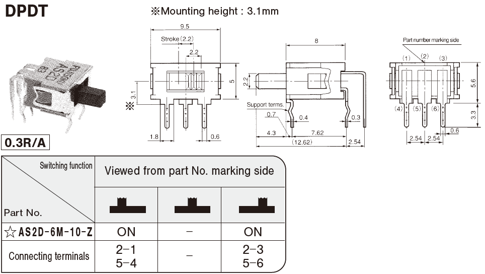
| Part No.:AS2D-6M-10-Z☆ | DPDT | R/A 0.3 inch pitch | ON - ON | |
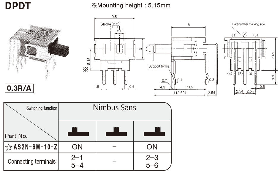
| Part No.:AS2N-6M-10-Z☆ | DPDT | R/A 0.3 inch pitch | ON - ON |
Outline Dimensions
Handling Precautions
Soldering Specifications
Manual Soldering / Device: Soldering iron 380℃, Max.; 3 seconds, Max.
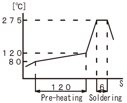
Auto Soldering / Device: Jet wave type or dip type 275 ℃, Max.; 6 seconds, Max.
Pre-heating should be done at temperatures ranging from 80 ℃ to 120 ℃ and within 120 sec.
Flux Cleaning
Solvent : Fluorine or Alcohol type.
Cleaning after soldering should be done after the terminal temperature falls to 90 ℃ or below, or after leaving the switch for five minutes or longer at room temperature.
Do not use ultrasonic cleaning system
Mounting of Switch
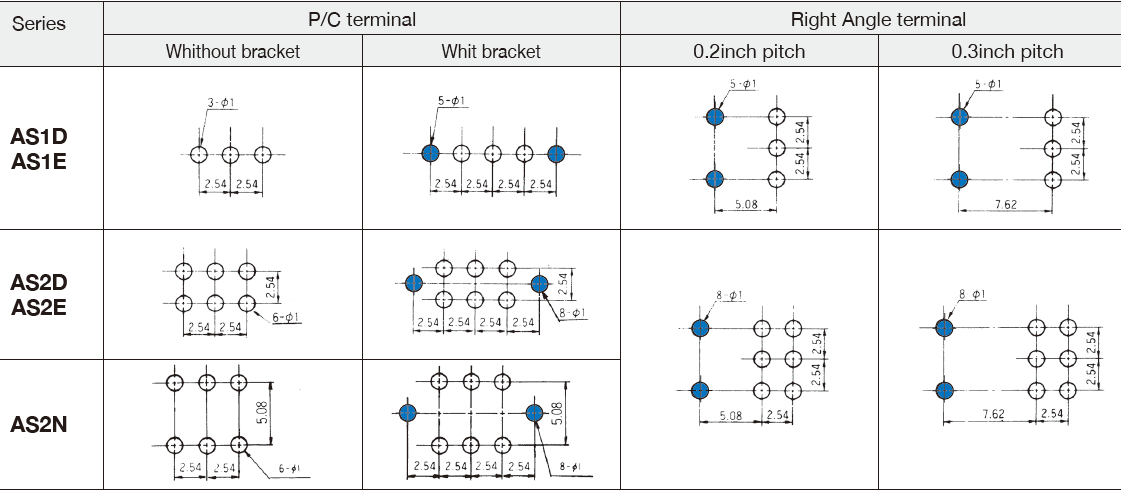
Use the PC boards of φ1 holes.
Do not bend the terminals before mounting the switch on the PC board.
After mounting the switch, do not place the device in such a way that the device weight will be applied on the knob, etc. of the switch.
Do not apply load exceeding 12.7 N (1.3 kgf) to the knob. Use a bracket (optional accessory) if the load is expected to exceed 12.7 N (1.3 kgf). The strength of the knob will be reinforced to 29.4 N (3 kgf) max..
PC Hole Layouts
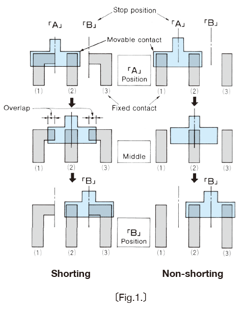
Shorting (Make-Before-Break)
A switch which momentarily connects both circuits when the actuator is moved from Point A to B in the below fi gure.
All switches which are not marked as “Shorting” are “Non-shorting” (Break-Before-Make).
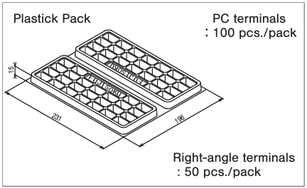
Packaging specifications
(Unit:mm)
Documents
Environmental files
- ●The above contents and descriptions are subject to change without notice.
