


Rotary encoders RE20F

-
●To buy this product, please go to the following Online Web stores.


COMPACT TWO-PHASE OUTPUT
- Compact, dia.: 20 mm
- Low torque, low inertia
- RoHS compliant
PART NUMBER DESIGNATION
| RE20F- | 100- | 1 | 0 | 0 |
|---|---|---|---|---|
|
Series name |
Resolution (P/R) 100, 300 |
Output phase 1: “A” only 2: “A” & “B” (100 P/R only) |
|
|
LIST OF PART NUMBERS
|
Part number | Output phases | Resolution | CAD |
|---|---|---|---|
| RE20F-100-100 | “A” only | 100 (P/R) |
|
| RE20F-300-100 | “A” only | 300 (P/R) | |
| RE20F-100-200 | “A” & “B” | 100 (P/R) |
ELECTRICAL CHARACTERISTICS
| Output phases | 1 phase “A” only | 2 phase “A” & “B” |
|---|---|---|
| Photo-sensor maximum current | 45 mA maximum (at 25 °C) | |
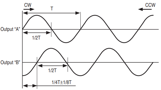
| Output wave form | Quasi-sinusoidal | |
| Output phases | A | A, B |
| Resolution (P/R) | 100, 300 | 100 |
| Phase difference of outputs A & B | ——— | 90° ± 45° |
| Maximum frequency response | ——— | 12 kHz |
| Output signal | 150 mVp-p minimum ※1 | 1 Vp-p minimum |
| Output signal amplitude variation ※2 | 40 % maximum | |
| Light source | LED | |
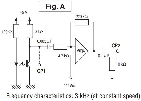
※ 1 Measured at CP1 in the fig.A of ‘MEASUREMENT CIRCUIT’ on the following page.
※ 2 One phase only : Measured at CP2 in the fig.A of ‘MEASUREMENT CIRCUIT’ on the following page.
※ 2 One phase only : Measured at CP2 in the fig.A of ‘MEASUREMENT CIRCUIT’ on the following page.
MECHANICAL CHARACTERISTICS
| Starting torque | 0.05 mN·m {0.5 gf·cm} maximum | ||
|---|---|---|---|
| Inertia | 0.2 g·cm2 maximum | ||
| Shaft loading (When mounting) | Radial | 1.96 N {200 gf} maximum | |
| Axial | 4.9 N {500 gf} maximum | ||
| Net weight | Approx. 15 g | ||
ENVIRONMENTAL CHARACTERISTICS
| Operating temp. range | 0 ~ 50 °C |
|---|---|
| Storage temp. range | - 20 ~ 80 °C |
| Protection grade | IP40 |
RELIABILITY TEST
| Test item | Test conditions | ||
|---|---|---|---|
| Vibration | Power OFF |
Amplitude : 1.52 mm or 98.1 m/s2 (10 G) whichever is smaller. |
|
| Shock | Power OFF | 1 time each in 6 directions (X, Y, Z) at 490 m/s2 (50 G), 11 ms. | |
| High temperature exposure | Power OFF | 80 °C 96 h | (To be measured after leaving samples for 1h at normal temperature and humidity after the test.) |
| Power ON | 50 °C 96 h | ||
| Low temperature exposure | Power OFF | - 20 °C 96 h | |
| Power ON | 0 °C 96 h | ||
| Humidity | Power OFF | 40 °C Relative humidity 90 ~ 95 % 96 h (To be measured after wiping out moisture and leaving samples for 1h at normal temperature and humidity after the test.) |
|
| Thermal shock | Power OFF | To be done 10 cycles with the following condition (To be measured after leaving samples for 1 h at normal temperature and humidity after the test.) 70 °C 1 h、- 20 °C 1 h |
|
OUTPUT
EXTERNAL SCHEMATICS
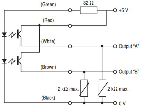
⦿ 2 phase 100 P/R
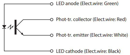
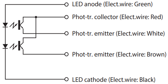
INTERNAL CIRCUIT
⦿ 1 phase 100・300 P/R
⦿ 2 phases 100 P/R
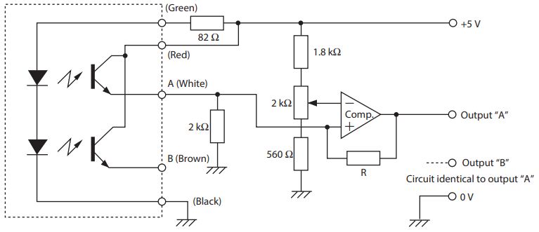
MEASUREMENT CIRCUIT
⦿ 1 phase 100・300 P/R
⦿ 2 phases 100 P/R
RATINGS
⦿ LED(at 25 °C)
| Maximum current | 45 mA |
|---|---|
| Reverse voltage | 4 V |
| Power dissipation (PD) | 75 mW |
| Temp. derating of PD (25 ~ 60 °C) | - 1.4 mW / °C |
⦿ Photo-sensor(at 25 °C)
| Collector current | 20 mA |
|---|---|
| Collector to emitter voltage (forward) | 20 V |
| Collector to emitter voltage (reverse) | 5 V |
| Collector dissipation (PD) | 75 mW |
| Temp. derating of PD(25 ~ 60 °C) | −1.0 mW/°C |
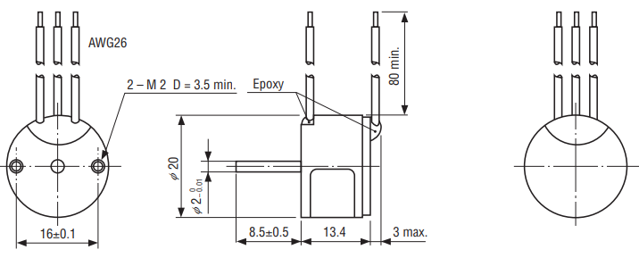
OUTLINE DIMENSIONS
Unless otherwise specified, tolerance: ± 0.4 (Unit: mm)
Documents
- ●The above contents and descriptions are subject to change without notice.
