


Micro Blowers Special Feature
- Our compact, lightweight micro blowers deliver exceptional longevity,
ultra‑low vibration, and high static pressure
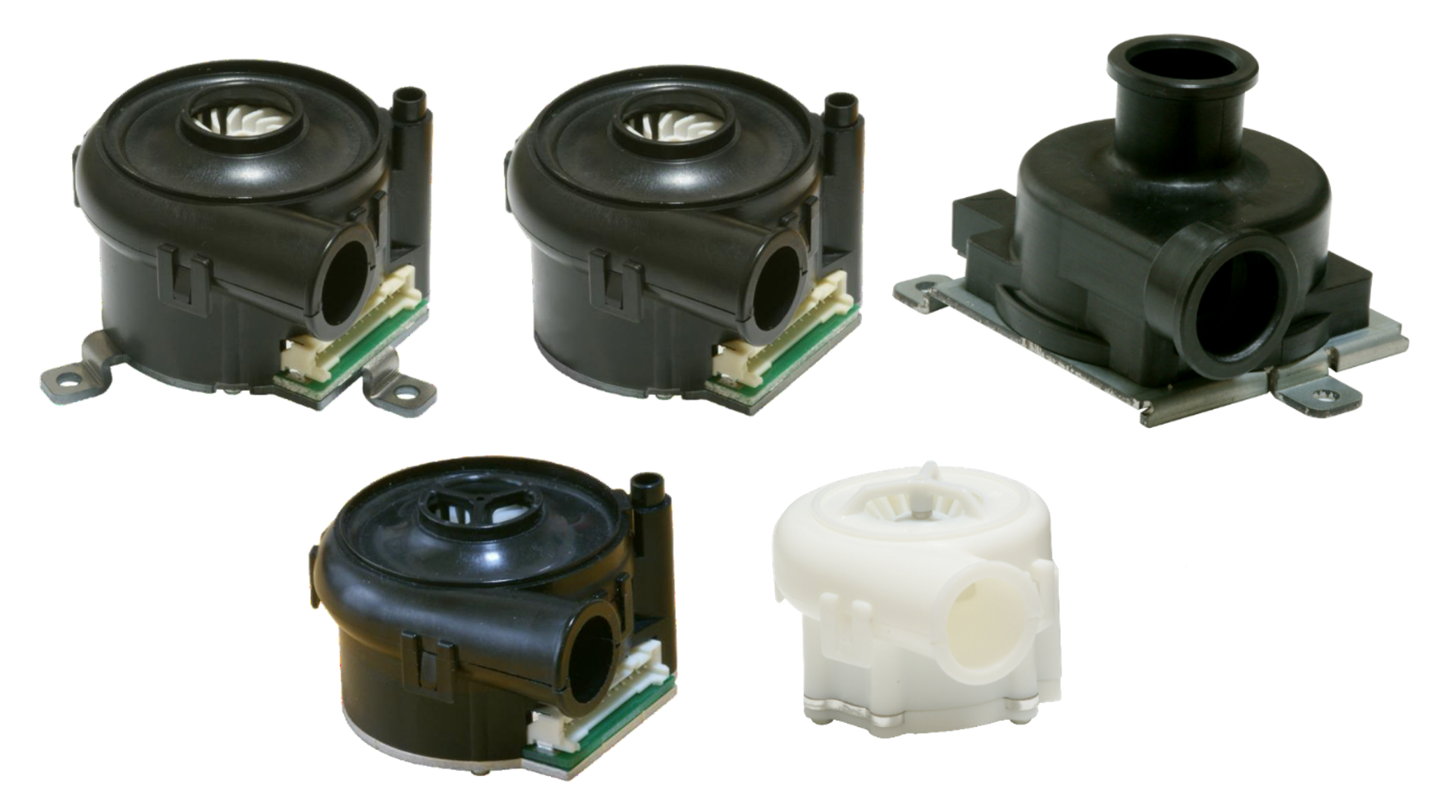
There are many types of fans, such as axial fans and centrifugal (turbo) fans. The micro blower introduced here is a turbo fan that employs our proprietary air dynamic bearing technology. Despite its ultra‑compact and lightweight form, it delivers strong airflow along with outstanding durability and remarkably low vibration. The following sections provide a detailed look at its high‑performance features.
- - Contents -
- 1. Structures / Features
- 2. Specifications
- 3. Applications & Uses
- ~ TF037 Series ~
- ~ TF029 Series ~
- 4. Set sales
- 5. Connection Method
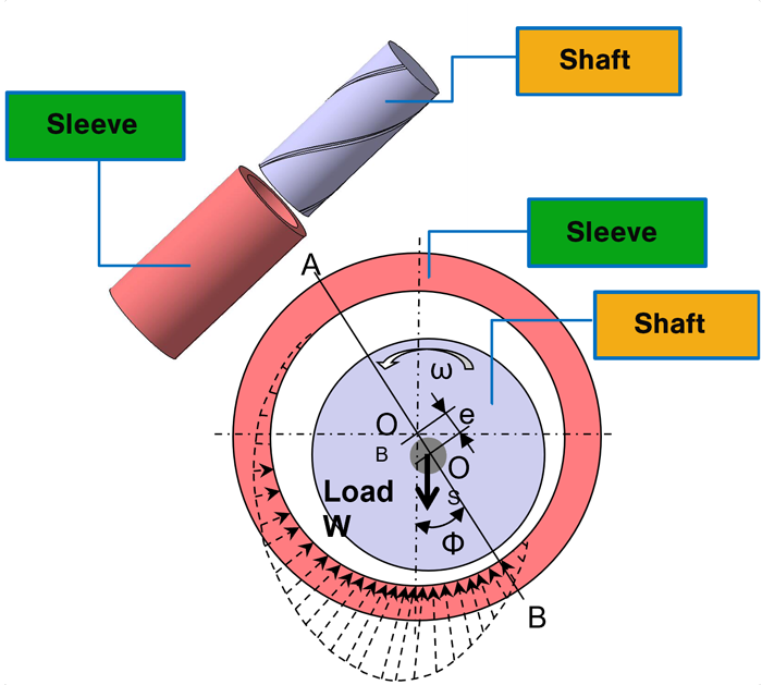
Air Dynamic Bearing: The Core Technology Behind Our Micro Blower
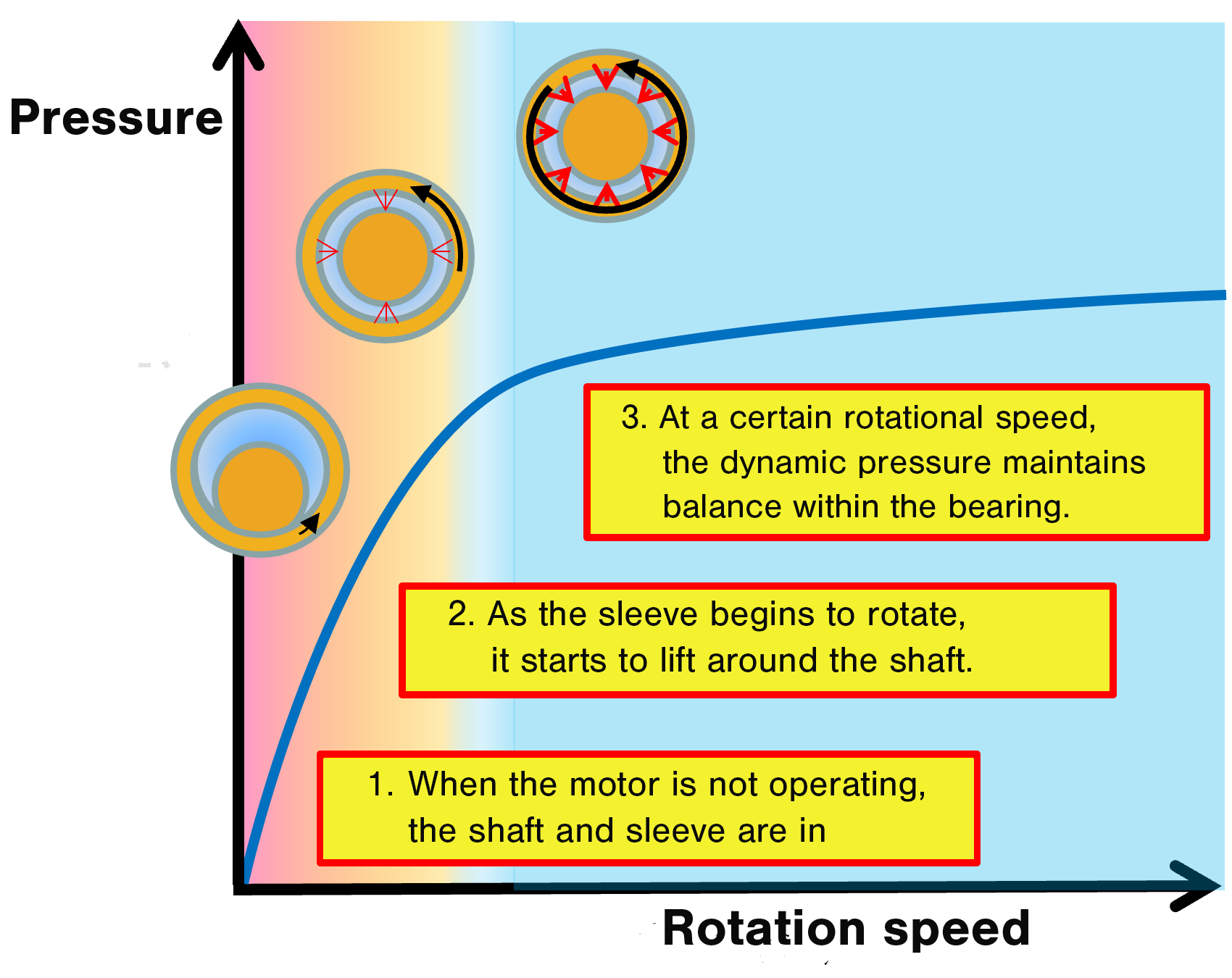
Our proprietary air dynamic bearing features a non‑contact structure in which the shaft and sleeve remain separated during micro‑blower operation. This non‑contact state, created by high‑speed rotation, eliminates wear between the shaft and sleeve, enabling high static pressure, long service life, and low noise.
-
※The diagram below is for visual reference※The diagram below is for visual reference
-
High Power, Long Life, and Low Vibration
- Long Life
-
Unlike conventional ball or oil‑impregnated bearings, whose lifespans degrade with temperature, our air dynamic bearing technology shows no such temperature sensitivity and can operate virtually indefinitely, provided the bearing materials do not deteriorate.
- Because our air dynamic bearing technology contains no oil, there is no risk of leakage. This oil‑free design is also more environmentally friendly.
- The non‑contact design of the air dynamic bearing, combined with optimized balancing, delivers significantly lower vibration levels than other bearing types.
- Ultra‑high‑speed rotation enables airflow and static pressure levels unattainable with other bearing types.
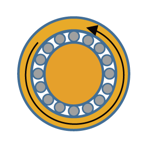 Ball Bearing
 Oil Bearing
 Air Dynamic Bearing
In the rotor blade section, our compact impeller featuring a proprietary design achieves low noise and also contributes to higher static pressure.
- Powerful Performance with High Static Pressure
- See it inflate air mats, blow away water droplets, and generate high static pressure powerful enough to lift a baseball.
- Remarkably Low Vibration
- This video compares our blower’s vibration levels with competing models using a simple coin test. A transparent cup highlights the vibration behavior clearly—take a look!
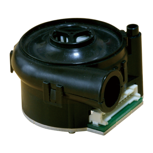
Ultra‑Compact, Ultra‑Lightweight
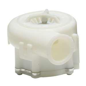
Another standout feature of our micro blowers is their compact, lightweight design. The TF029 series is exceptionally light at just 55 g, making it suitable even for use in CPAP devices. The TF037 series, weighing between 72 and 165 g, is similarly lightweight and well‑suited for applications such as fuel cell systems.

TF037 Series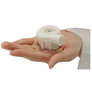
TF029 Series
Specifications
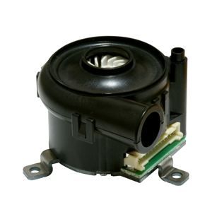
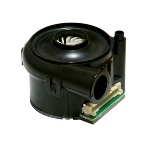
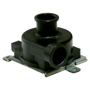
| Part number | TF037C-2100-F | TF037C-2000-F | TF037E-2000-F | TF037F-2000-F | TF029B-1000F |
|---|---|---|---|---|---|
| Photo |
|
|
|
|
|
| Operating Voltage Range | 10 ~ 30 VDC | 12 ~ 27 VDC | |||
| Rated Supply Current | 0.9 A Max. | 0.62 A Max. (24 VDC) | |||
| Rated Power | 21.6 W Max. | 14.9 W Max. (24 VDC) | |||
| Operating Speed | 6,000 ~ 45,000 rpm | 36,000 rpm | |||
| Minimum Airflow | 5 L / min | 10 L / min | |||
| Maximum Rotational Speed | 45,000 r / min | 50000 r / min | |||
| Noise Level | 65.0 dB (A) Max. | ||||
| Weight | 94 g | 90 g | 165 g | 72 g | 55 g |
| Fixing legs | With | Without | Without | Without | Without |
| Applications | General Industrial Applications |
General Industrial Applications |
Fuel Cell Applications ※P14 Quick Fastener |
Large CPAP Applications | Small CPAP Applications |
| Remarks | Uses UL94 V-0 certified resin materials | Uses FDA‑compliant resin materials | |||
- The pressure and airflow values are provided for reference only and are not guaranteed.
Characteristic Curves
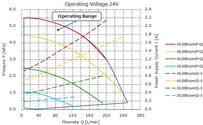
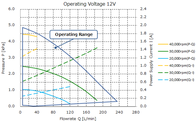
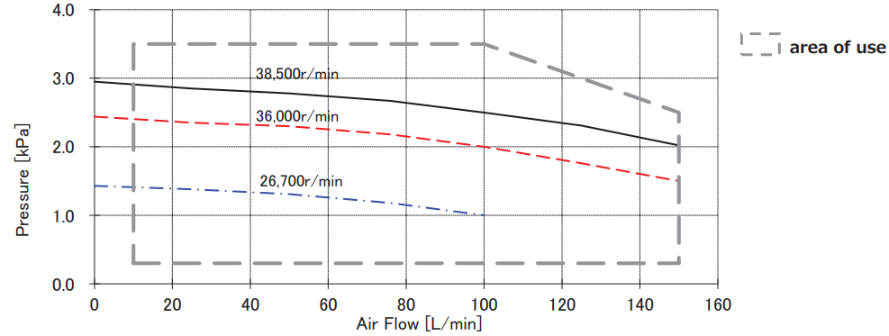
TF037 Series
⦿ 24V P-Q/Q-I Characteristics
⦿ 12V P-Q/Q-I Characteristics
TF029 Series
⦿ 24V P-Q/Q-I Characteristics
⦿ 12V P-Q/Q-I Characteristics
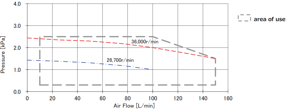
- The above P–Q curve illustrates how pressure and airflow vary with changes in flow load.
- Please note that the pressure and airflow values are for reference only and are not guaranteed.
Applications & Uses
- See how our micro blowers are used in household fuel cell systems, where they are already widely adopted.
- For CPAP applications, we demonstrate how our micro blowers are built into the device, including a human body model to show how they function in real use.
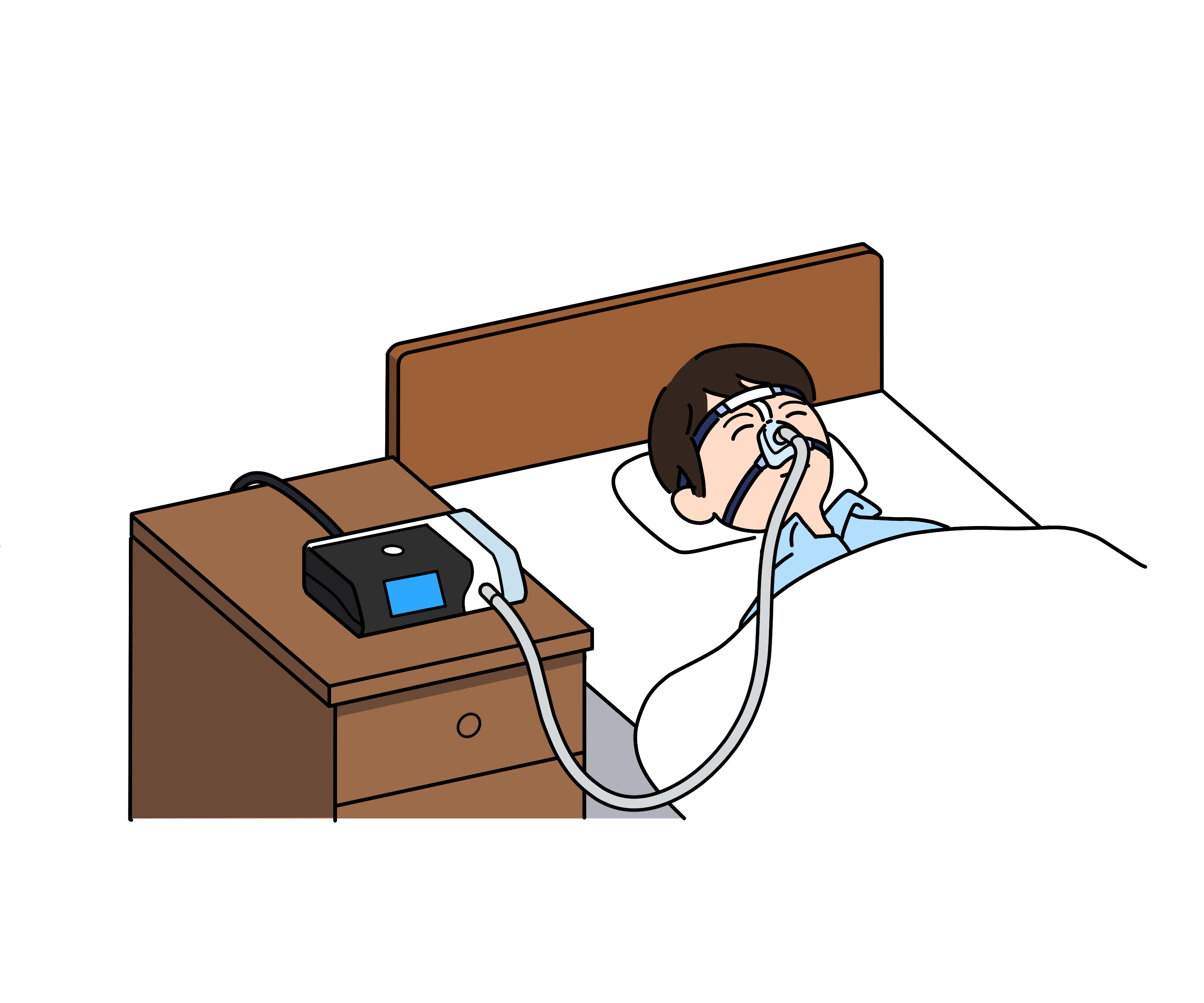
CPAP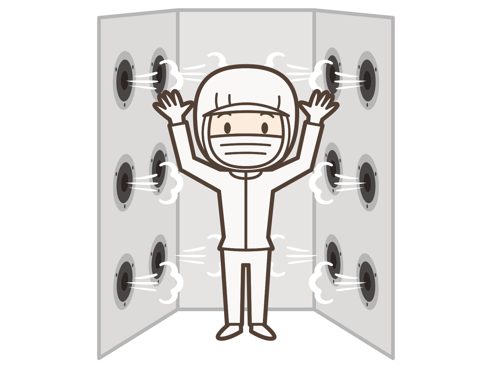
Air shower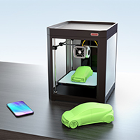
3D Printer
Server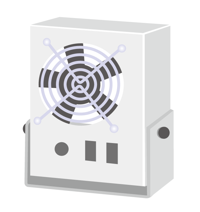
Ionizer
Attractions
※It’s also ideal for applications such as blowing dust out of commercial printers.
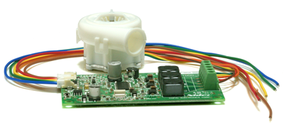
Set Sales
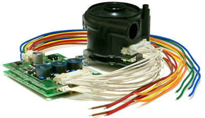
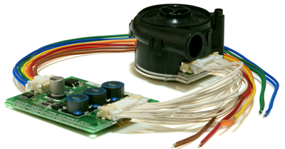
- For prototyping and evaluation, we also offer a complete set that includes the main unit, driver, and harness.
| Model | TF037C-2100-P | ||||
|---|---|---|---|---|---|
| Included Items | Micro Blower Main Unit | TF037C-2100-F | |||
| Driver | TF037-1001-D | ||||
| Harness⓵ | For Micro Blower Driver Connection | ||||
| Harness② | For Driver Power Connection | ||||
| Model |
TF037F-2000-P | ||||
|---|---|---|---|---|---|
| Included Items | Micro Blower Main Unit | TF037F-2000-F | |||
| Driver | TF037-1001-D | ||||
| Harness⓵ | For Micro Blower Driver Connection | ||||
| Harness② | For Driver Power Connection | ||||
| Model | TF029B-1000-P | ||||
|---|---|---|---|---|---|
| Included Items | Micro Blower Main Unit | TF029B-1000-F | |||
| Driver | TF029B-1001-D | ||||
| Harness | For Micro Blower Driver Connection | ||||
- The TF029B set includes only one harness for the driver–power connection, as the driver leads are directly wired from the micro blower.
Connection Method
- Prepare two DC power supplies and wire them as shown in the diagram below.
- Power Supply 1 is used for the drive circuit, and it should be set to 24 VDC.
(A current capacity of 3 A or higher is recommended.) - Power Supply 2 is used for speed control. Adjust the voltage between 1 V and 5 V to change the rotational speed. This completes the wiring and voltage settings required for basic blower operation.
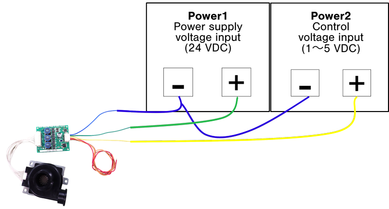
- The brown, red, and orange wires shown in the diagram below are not required for basic operation. They are used for error output, braking, and speed monitoring.
| Terminal Number (Harness Side) | Wire Color | Terminal | Connection |
|---|---|---|---|
| 1 | Brown | Error | Error Output |
| 2 | Red | FG | Speed Signal Output |
| 3 | Orange | BR | Short brake |
| 4 | Yellow | CNT | Control voltage input |
| 5 | Green | Vcc | Power Voltage Input |
| 6 | Blue | GND | GND |
